
Discrete 0.5-300 ms Monostable Multivibrator
The monostable multivibrator circuit operates by producing a single output pulse in response to a triggering event. The primary components involved include a capacitor, resistors, and transistors, which work together to define the duration of the output pulse. In this configuration, CR1 serves as a critical component that allows the input signal to control the operation of the circuit without directly influencing the output, thanks to its open collector configuration.
When the input signal is applied, CR1 activates TR1, which momentarily connects the input to ground. This action causes a change in voltage across the timing capacitor, which is charged through the resistor R5. The value of R5, in conjunction with the capacitor, determines the time constant of the circuit, thereby controlling the pulse width. The use of a 1M trimmer potentiometer allows for fine adjustments to the resistance, enabling precise control over the timing characteristics of the output pulse.
The output pulse is taken from the collector of TR2, which acts as the final stage of the circuit. The output can be utilized to drive other components or circuits, making this monostable multivibrator versatile for various applications, such as timers, pulse generation, or signal conditioning. The design ensures that the output remains stable and predictable, provided the input trigger is properly managed.
The schematic diagram accompanying the description illustrates the component layout and connections, providing a visual aid for understanding the circuit's functionality and interrelationships between components. This detailed overview emphasizes the importance of each component and their roles in achieving the desired pulse width and circuit behavior.Monostable multivibrator circuit produce a fixed pulse-width when the input is triggered. The input is fed to CR1, which should be an open collector source since the TR1 would short the input to ground during the active state appear on this circuit`s output. The output of this circuit is tapped from the collector of TR2. This monostable multivi brator output pulse width can be varied from 0. 5 to 300 milliseconds, adjusted by a 1M trimmer potentiometer R5. Here is the schematic diagram of the circuit: 🔗 External reference
Related Circuits
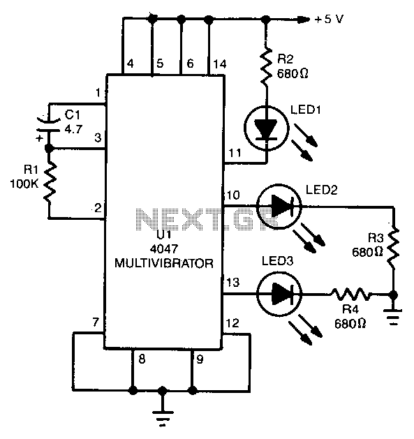
The 4047 is configured as a free-running astable multivibrator (oscillator) circuit. This configuration offers three different outputs. The output pulses at the Q and Q output (pins 10 and 11, respectively) are the same as in the previous two...
This discrete voltage regulator features capabilities equivalent to modern voltage regulator integrated circuits (ICs). While constructing a discrete version may not be cost-effective, studying the schematic diagram provides valuable insights into its operation. The circuit includes a resistor of...
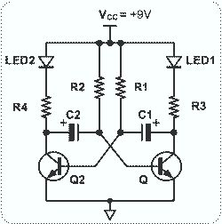
This circuit is straightforward and easy to construct, utilizing two transistors as active components along with several passive components such as resistors, capacitors, and two LEDs. The circuit employs the MPS2222 transistor, though any NPN type transistor can be...
What exactly is a multivibrator? I suppose one definition would be 'a circuit which has several states'. This will do for now, it's quite loose so leaves plenty to the imagination! Conventional multivibrators have only two stages and come...
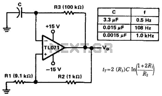
When this circuit is activated, the inherent offset of the devices acts as an automatic starting voltage. The output voltage V0 becomes positive, and the positive feedback through R2 and R1 drives the output to saturation. The elevated voltage...
This circuit is straightforward. The initial 555 timer prevents the second timer from being activated while the first is operational. Drive the circuit with a simple 12-volt power supply. The circuit utilizes two 555 timer integrated circuits (ICs) configured in...
Warning: include(partials/cookie-banner.php): Failed to open stream: Permission denied in /var/www/html/nextgr/view-circuit.php on line 713
Warning: include(): Failed opening 'partials/cookie-banner.php' for inclusion (include_path='.:/usr/share/php') in /var/www/html/nextgr/view-circuit.php on line 713