
Discrete Robot

Resistors R1 and R2 in combination with light-dependent resistors LDR1 and LDR2 form a voltage divider (with the current being limited by R1 and R2 for bright light). Window discriminator TCA965 compares the mid-point voltage with an upper threshold value (adjustable using P1) and a lower threshold value (adjustable using P2). Outputs AU, AI, AO, and AA go High if the voltage lies below, inside, above or outside this window, respectively; otherwise they remain Low.
Output AA switches transistor T1, which drives the right-hand motor. The light-dependent resistors can be attached on the left and right sides of the vehicle, or at the front and rear. This causes the robot to turn to the right, due to the motor on one side being stopped, until the desired lighting relationship is restored.
The vehicle will then continue to travel in a straight line until the lighting relationship again changes, at which point it will again turn, and so on. You can experiment with various behaviour patterns by using the other outputs of the window discriminator.
If a transistor is provided for each of the AU and AO outputs of the TCA965, the robot can be made to travel toward or away from a light source, depending on the connections. Using the window discriminator, the robot will operate under the rules of a three-point controller (left, straight ahead, or right).
If you fit the light-dependent resistors in a box under the vehicle together with a light source, you can try to have the robot follow a black line on a white background. A reflective IR sensor enables the robot to respond to obstacles. This not as simple as it might seem, since the Sharp IS471 operates the IR LED with pulsed light and uses sophisticated detection processing.
When an obstacle is detected, the output (pin 2) goes Low and blocks transistor T2. This causes the motor to stop, and the vehicle will rotate about the stationary wheel until the obstacle is no longer in its path. The sensitivity of the IS471 can be set using P3. As its range is only around 10 15 cm, the vehicle must not travel too quickly, since otherwise it will not be able to avoid obstacles in time.
This part of the circuit is also open for experimentation. If a relatively large and fast robot requires an obstacle detector (or isn`t fitted with the IS471), an ultrasonic detector can also be used. Suitable complete construction kits are available from Conrad, for example. You can also fit a suitable mechanical pushbutton switch mounted on a flexible rod. The obstacle detector can also drive a warning buzzer or a lamp; the circuit leaves lots of room for your own ideas.
The circuit works over a wide range of supply voltages from 4. 5 to 16 V. If larger motors are used, transistors with increased power-handling capacity and heavier batteries are necessary. The author connected two 4. 8-V rechargeable batteries in series and used BC388 transistors as drivers for Lego micromotors. You can build the robot entirely according to what you have in your parts box. The mechanical elements can also be freely selected, but they partially determine the behaviour and operation of the robot.
The author`s robot is made from a Lego chassis with a prototyping board holding the circuitry attached using elastic bands. The motors are fitted on the left-hand and right-hand sides. The third wheel at the front can turn freely. One problem must be mentioned: if an obstacle is detected while an incorrect lighting relationship is present, the vehicle remains standing.
In this case, a bit of logic could be added to cause both motors to rotate in reverse. However, that would require directional switches for the motors or motor driver ICs (L293D) 🔗 External reference
Related Circuits

It is a common misconception that a robot voice generator box necessitates a large number of integrated circuits (ICs). In reality, the ISD2500 ChipCorder family of ICs from Winbond can effectively fulfill this requirement. The ISD2500 ChipCorder series represents a...
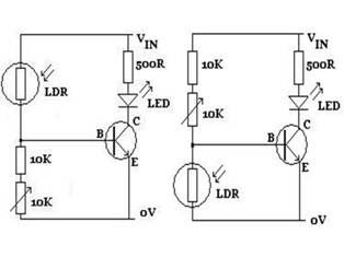
The figures above illustrate the fundamental concept of a robot, which consists of various input and output devices connected to a central processing unit, commonly referred to as the brain. These inputs and outputs are essential for the robot's functionality...
This doorbell circuit generates a low tone that transitions to a higher frequency. The total equivalent resistance connected between the base of Q1 and ground (Rbg), along with coupling capacitor C1, determines the frequency of the audio frequency (AF)...
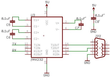
The UART, or Universal Asynchronous Receiver/Transmitter, is a feature of microcontrollers that facilitates serial data communication (text, numbers, etc.) with a PC. This device converts incoming parallel data (within the microcontroller/PC) to serial data that can be transmitted over...
When the 36 kHz infrared light emitted by the LEDs is reflected off an object, one of the receiver modules is activated. The PIC16F84 microcontroller then directs the robot to avoid the object by reversing one of the motors. The...
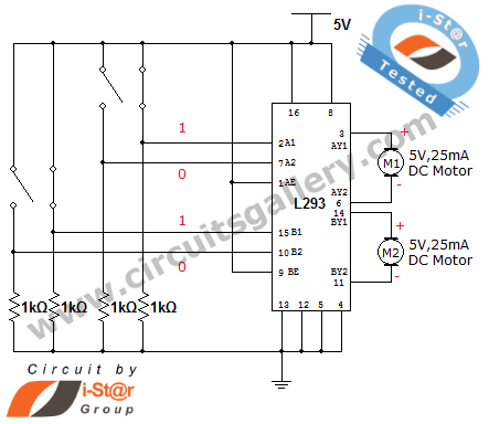
How can a DC motor be rotated in clockwise and counterclockwise directions? This is a common question posed by many robotics beginners. DC motor driver circuits are essential components in robotics workshops. The L293D IC is frequently utilized for...