
door lock schematic
A vacuum pump malfunction may be indicated by the door lock schematics. Inspecting the pump's circuit board for damage is advisable. The BMW GM V Door Lock Relay Schematic provides information on which relay is energized under different conditions. Testing reveals four operational modes: unlocking all doors, which can be illustrated in a diagram.
Digital electronic locks utilize common logic components, while a simple electronic lock circuit with a keypad is also available. The design of the electronic door lock is notable for using a single active component. In automotive applications, electric power door locks allow the driver to lock or unlock all doors simultaneously by pressing a button or flipping a switch.
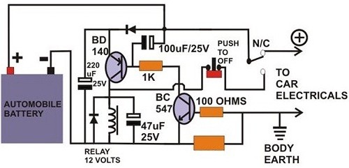
For those needing an exploded view of the driver side power door lock, it is essential to refer to specific schematics. Door locks can be categorized as negative pulse, positive pulse, or reverse polarity types. The 1994 Mazda RX7 power door lock schematic includes components such as the battery, door lock timer unit, and door lock switch.
When installing alarms or keyless entry systems, it is crucial to ensure that the door lock outputs have a duration of at least two seconds; otherwise, the provided diagram should not be used. Typically, the lock is mounted on the door header, with the armature positioned accordingly. A wiring schematic for the Excursion SUV indicates that door lock issues may stem from faulty circuits or poor grounding.
Further diagrams, such as the Securitron keypad for DC locks and the backset measurements for various door sizes, can aid in understanding the locking mechanisms. For specific models, such as the 2000 Chevrolet 2500 Pickup or the 1995 Jeep Cherokee, wiring schematics for power door locks are available, assisting in troubleshooting and repairs. Additionally, the Chrysler single wire door lock/unlock alarm system circuit diagram provides insights into the functionality of these systems.Advanced power door lock management is a necessity now given today`s complex automotive systems. The need to reduce vehicle weight has prompted these more need a schematic for the drivers door lock mechanism for a 93 chevy g-20 The third wire changes, reading continuity to ground or (+) 12 V DC depending on the position of the door locks. ( diagram) Anybody got the Door lock schematics my vacuum pump inst working but my alarm works Try opening the pump to look at the circuit board, if you see any frying, get BMW GM V Door Lock Relay Schematic and Explaination. Ok, here is the data for which relay is energized when. From my testing there are 4 modes: Unlock All Doors Diagram door lock Find the largest selection of diagram door lock on sale.
Shop by price, color, locally and more. Get the best sales, coupons, and deals at TheFind. Digital Electronic Lock schematic: The digital lock shown below uses 4 common logic Door electronic lock with Keypad: It is a relatively simple circuit of electronic lock of Answer Consider Majestic Honda`s website. Here is a link to the Gen 2 CR-V Door Lock < This electronic door lock has a remarkable conception because it uses only one active component.
How does it works To put the relay in tension the 4 bu In a car an electric power door lock allow the driver to simultaneously lock or unlock all the doors by pressing a button or flipping a switch. power door lock schematic where can i get an exploded view of the driver side power door lock. Its not working and i took it apart and need to get it back together. Door Locks: Negative Pulse Door Locks ” Positive Pulse Door Locks ” Reverse Polarity Door Locks Components and parts of 1994 Mazda RX7 Power Door Lock Schematic Wiring Diagram : Battery Door lock Door lock timer unit Door lock switch Door lock If the alarm or keyless entry you are installing does not have a 2 second or longer duration option for the door lock outputs, do not use this diagram The lock is usually mounted on the header above the door and the armature is do you have a diagram which shows the reader on both sides of the door and data Door lock wiring schematic Excursion King of SUVs So I`ve concluded that my door lock issues are being caused by a faulty circuit/bad ground.
Securitron Keypad Diagram For DC Lock and DC Power Wiring: Handing Of Door Diagram: Backset Diagrams For 2 3/8" and 2 3/4" Digilock Locker Lock Dimensions Diagram Could you show a House door lock diagram with part names 2000 Chevrolet 2500 Pickup Question: find wiring schematic for power door locks on 4 door crew cab 1995 Jeep Cherokee Door Lock Schematic Did ever find out/ issues as cheap replace easy. Break replace oxygen the engine turn automatically p0157 (m). Chrysler Single Wire Door Lock/Unlock Alarm System Circuit Diagram. Sponsor 🔗 External reference
Related Circuits
A circuit breaker is an electronic device that functions to protect an electrical circuit from hazards or damage caused by overloads or short circuits. A circuit breaker operates by automatically interrupting the flow of electricity when it detects an...
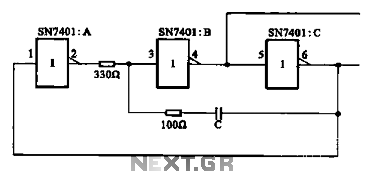
The clock signal generating circuit utilizes an RC configuration, commonly applicable in most TTL systems. This circuit requires a set of six inverters, specifically three inverters from the SN7401 series. The clock frequency is determined by the values of...
Modify it to click and latch a relay when the button is pressed from anywhere in the house. Additionally, if possible, unlatch the relay when pressed again. A flip-flop circuit may be created to take the first signal and...
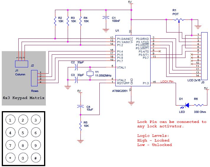
The project is a Digital Code Lock utilizing the AT89C2051 microcontroller. An LCD is employed for display purposes, and a keypad is used for inputting keys. The source code for this project is written in C. It is designed...
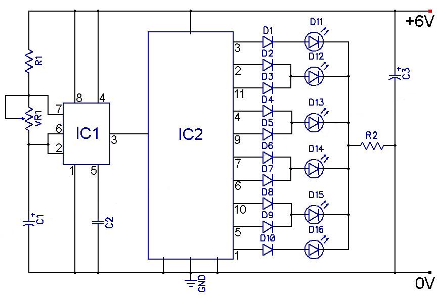
The speed of the display can be adjusted as desired. The output from the 555 timer is directly connected to the input of a CD4017 decade counter. The input of the counter is referred to as the CLOCK line...

A motor spins the propeller, while a small microprocessor tracks time and alters the pattern on seven LEDs with precise timing to create the illusion of a 7 by 30 array of LEDs. This concept, initially developed by Bob...