
propeller clock amazing illusion

The propeller clock operates on the principle of persistence of vision, where the rapid movement of the propeller combined with the synchronized illumination of the LEDs creates a visual effect that tricks the human eye into perceiving static images. The motor is typically a brushless DC motor, selected for its efficiency and ability to maintain a constant speed, which is crucial for the accurate timing necessary for the illusion to work effectively.
The PIC microcontroller is programmed with a specific algorithm that determines the timing of each LED based on the rotational speed of the propeller. The microcontroller receives input from the photo detectors, which detect the position of the propeller blades and provide feedback to ensure that the LEDs light up at the correct moment. The use of photo detectors minimizes the impact on the visual appearance of the clock, as they are discreetly placed and do not interfere with the spinning propeller's aesthetics.
The clock features multiple modes, including a digital display mode that shows numerical time and an analog mode that simulates clock hands. Users can switch between these modes through a user interface that may consist of buttons or touch sensors, designed to be accessible even while the clock is in motion. This innovative design not only enhances user experience but also showcases the advanced engineering involved in creating a visually captivating timepiece.
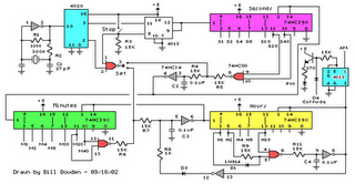
Overall, the propeller clock exemplifies a blend of mechanical and electronic engineering, demonstrating how precise timing, sensor integration, and visual effects can create an engaging and functional device.A motor spins the "propeller", and a small microprocessor keeps track of time and changes the pattern on seven LEDs with exact timing to simulate a 7 by 30 array of LEDs. It is an illusion, but it works nicely. Propeller clocks were to my knowledge first started by Bob Blick then many people started copying his idea and adding certain improvements
along the way. Propclocks are really pretty complex devices, utilizing a PIC microcomputer that performs instructions at 10mhz. The PIC is the brain of the device and does most of the work involved in making the LEDs light up at just the right time so that it appears there are numbers, and in the analog mode hands suspened in mid air.
On my version of the clock you change the mode and time setting while it is still spinning at about 1150 PRM. This is done through carefully alligned photo detectors and LEDs. These sensors are located on the rear of the spinning motor so they dont affect the look of the clock at all.
🔗 External reference
Related Circuits
The following circuit illustrates a Cat and Dog Repellent Timer Circuit Diagram. Features include the capability to maintain a deep cycle battery charged by a solar panel. The Cat and Dog Repellent Timer Circuit is designed to provide a humane...
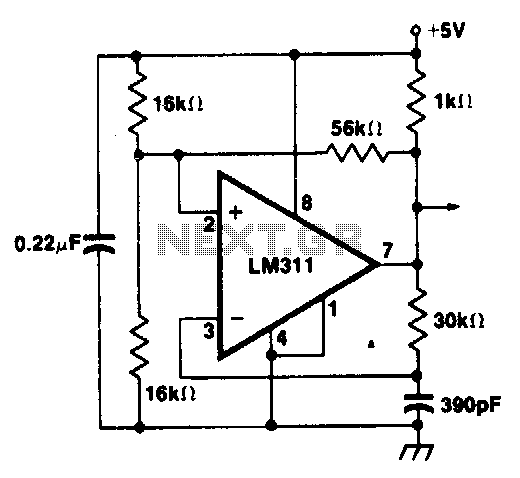
A clock source using the LM311 voltage comparator in positive feedback mode to minimize clock frequency shift problems. The proposed circuit utilizes the LM311 voltage comparator configured in a positive feedback arrangement to generate a stable clock signal. The LM311...
Last year, I found a 31 day pendulum wall clock (disassembled) in a box of parts at a swap meet and decided to try and put it together and regulate it with a quartz crystal oscillator. The escapement part...
A clock-and-data recovery (CDR) circuit is utilized to recover the clock from a transmitted data stream and re-time that data with the recovered clock. These circuits are generally positioned at the front-end of receiver chips to extract the clock...

The Pyro Propeller Clock POV schematic is relatively straightforward. It consists of three primary components: the power supply utilizing a 7805 voltage regulator, the LED output control managed by a PIC18F252 microcontroller and a 74LS373 latch, and the 'home'...
A multiplexed display suitable for LED readouts is provided by a circuit that uses TTL counters to count a 60-Hz line. When the count reaches the hour mark, flip-flop M is set on every cycle. Gate G3 then detects...