
Doorbell MemoryCircuit
The electronic doorbell memory circuit is designed for simplicity and efficiency, making it an accessible project for hobbyists and electronics enthusiasts. The core components include two transistors (one NPN and one PNP), a diode, a capacitor, an LED, a switch, and a resistor. The transistors function as switches that control the flow of current based on the doorbell's activation. The diode ensures that the circuit can handle either AC or DC input, making it versatile for various doorbell types.
The power supply, consisting of two 1.5-V batteries, is chosen for its compact size and longevity. The low current consumption of the circuit means that the batteries can last several years, making it practical for everyday use. The use of a capacitor to initially block current flow until the system is armed adds a layer of reliability, ensuring that the LED only lights up when the doorbell is pressed.
The design allows for easy assembly on a perforated prototyping board, which can be cut to fit within the casing of an existing doorbell. This makes it an ideal project for those looking to enhance their doorbell system without needing specialized equipment or extensive knowledge of electronics. Overall, this electronic doorbell memory circuit is a valuable addition to any home, providing peace of mind and convenience for users.If you`re expecting an important visitor but you just have to step out for a moment, an electronic doorbell memory can come in handy so you can see whether someone rang while you were out. Of course, you can`t tell whether it was the visitor you were expecting who dropped by then, but a call to the mobile phone of the person concerned can quickly
answer that question. A doorbell memory can also save you the trouble of going to the front door (if you live upstairs) when you think you heard the bell but aren`t sure. And if you can`t buy one, then of course you can build one yourself! Read on to find out how. It takes only a handful of electronic components to build a handy tale-tale with an LED that indicates whether someone pressed the button of your doorbell.
How many times have you thought you heard your doorbell while watching television in the evening The sound of the well-known ding dong` chimes occurs all too often, especially during the many commercials that nowadays remind us at the most inconvenient times that the gripping film we`re watching is only a fantasy. A glance at the LED of the doorbell memory will tell you whether you have to go to the door or can try to escape the ads by zapping to a different channel.
Or if you`re expecting someone but have to make a quick trip to the neighbors to borrow a few beers for the occasion, it can be handy to be able to see whether your visitor already arrived while you were out. If so, you can always call him or her on the mobile to confess that you hadn`t properly prepared for the expected visit.
The circuit is as simple as it is effective. It is connected in parallel with the bell and powered by a 3-V supply formed by two 1. 5-V penlight batteries connected in series. The doorbell memory draws so little current that a set of batteries will last several years in normal use. The circuit works as follows. When the supply voltage is switched on with switch S1, capacitor C1 (initially uncharged) prevents transistors T1 and T2 from conducting.
LED D2 is off, and the memory is armed. When the doorbell button is pressed, the memory circuit receives an AC or DC voltage via diode D1, depending on the type of doorbell. It can handle either type. Transistor T1 thus receives a base current, so it starts conducting and drives T2 into conduction. The LED lights up as an indication that the doorbell has rung (i. e. was energized). The combination of transistor T2 and resistor R3 keeps T1 conducting after the bell voltage goes away (when the button is no longer pressed).
The memory remains in this state until switch S1 is opened. This switch thus acts as a reset switch as well as a power switch. The circuit can be assembled compactly on a small piece of perforated prototyping board, so it can be fitted into just about any model of doorbell. The transistors can be replaced by other, equivalent types as long as you use a combination of NPN and PNP types.
🔗 External reference
Related Circuits
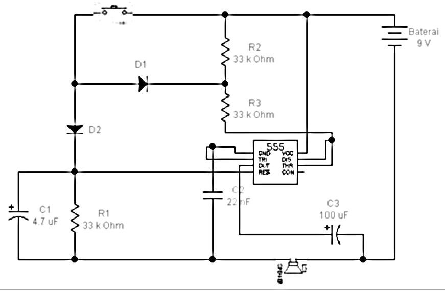
This circuit is a musical doorbell. When the button S1 is pressed, a short melody plays. If the button is pressed multiple times in quick succession or held down, a different melody is generated, and the melody plays for...
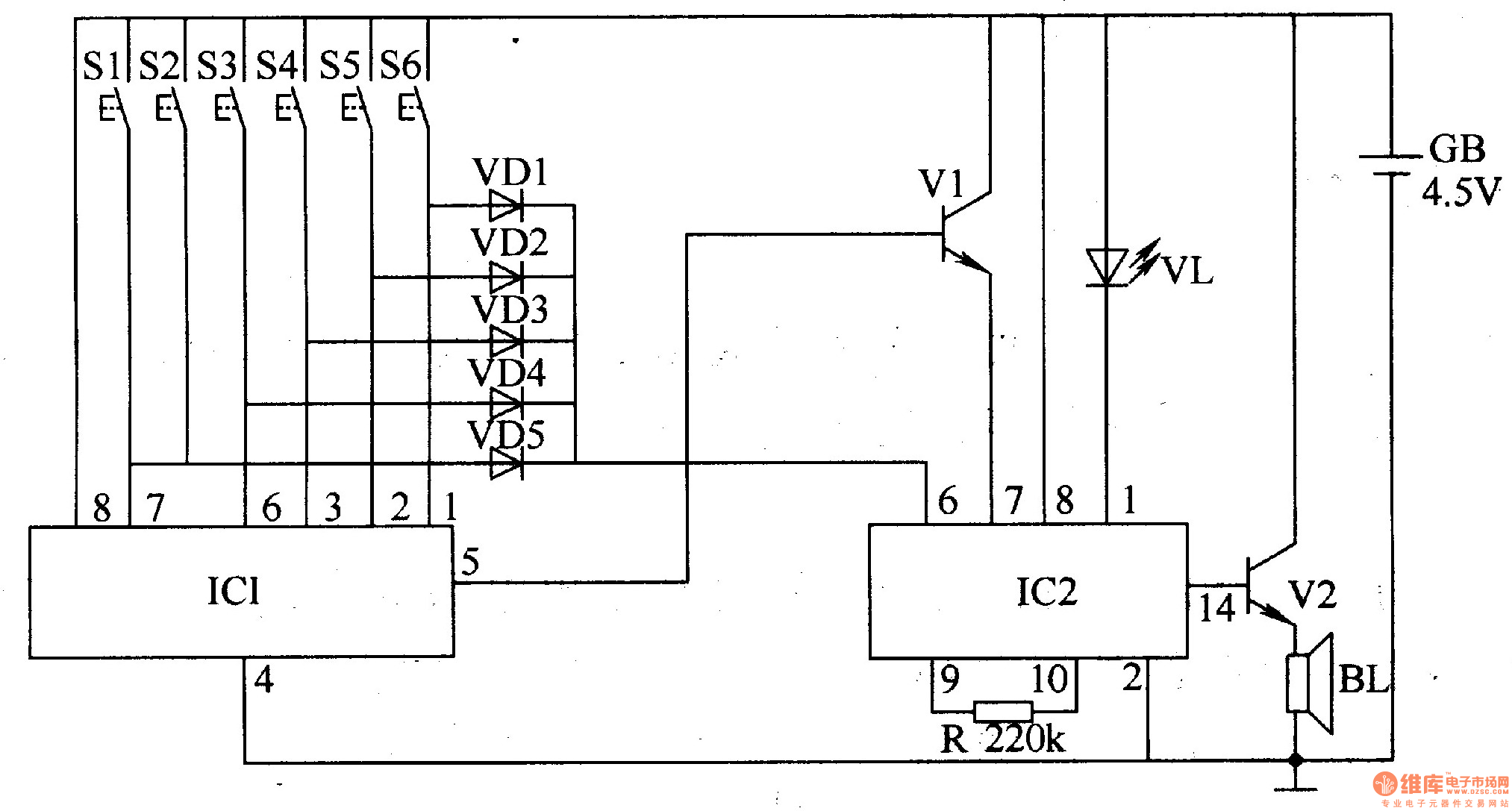
The electronic doorbell circuit utilizes a password mechanism and includes both an electronic password circuit and a music generation circuit, as illustrated in Figure 3-118. The electronic password circuit is comprised of integrated circuit IC1, keys S1-S6, and diodes...
This circuit utilizes a synthesized sound chip from Holtek, the HT-2811, which produces the sound of a "ding-dong" chiming doorbell. Additionally, it incorporates a CMOS 4026 counter display driver integrated circuit (IC) to tally the number of visitors. The...
All components are arranged as depicted in the sequence below. Current will flow from the source voltage to the switch. When the switch is closed, current will flow through the diode, which acts as a closed switch due to...
This simple and cost-effective ding-dong electronic doorbell circuit is based on IC 8021-2. The IC has an integrated circuitry that generates a ding-dong sound each time its pin 3 is pulled low. The sound is stored in the IC...
When the doorbell switch K1 is pressed, the doorbell rings and LED D3 lights up. If there is no one to answer the door, guests will leave, but D3 remains illuminated, indicating that visitors have arrived. The circuit includes...
Warning: include(partials/cookie-banner.php): Failed to open stream: Permission denied in /var/www/html/nextgr/view-circuit.php on line 713
Warning: include(): Failed opening 'partials/cookie-banner.php' for inclusion (include_path='.:/usr/share/php') in /var/www/html/nextgr/view-circuit.php on line 713