
Doubling rectifier circuit in negative ion generator application circuit
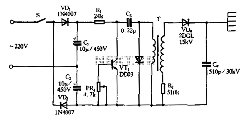
The doubling rectifier circuit is an essential component in negative ion generator applications, where it plays a crucial role in converting alternating current (AC) to direct current (DC) while also increasing the voltage level. This circuit typically utilizes a combination of diodes and capacitors to achieve its rectification and voltage doubling functions.
In a standard configuration, the circuit consists of two diodes arranged in a full-wave rectifier setup. The input AC voltage is applied to the anodes of the diodes, which allows current to flow through them during both halves of the AC cycle. The output from the cathodes of the diodes is then smoothed by a capacitor, which helps to reduce the ripple in the DC output.
To achieve voltage doubling, an additional capacitor is employed to store energy during the rectification process. When the AC voltage reaches its peak, the first diode conducts and charges the capacitor. During the next half cycle, the second diode becomes forward-biased, allowing the capacitor to discharge and effectively doubling the output voltage.
This configuration is particularly advantageous in negative ion generator circuits, as it provides the high voltage necessary for ionization processes while maintaining a compact design. The use of high-voltage rated diodes and capacitors is critical to ensure reliability and efficiency in the circuit operation.
Overall, the doubling rectifier circuit is integral to the performance of negative ion generators, enabling them to produce the desired ion concentration levels for various applications, including air purification and environmental enhancement. Proper selection of components and careful circuit design are essential to optimize the performance and longevity of the system.Doubling rectifier circuit in negative ion generator application circuit
Related Circuits
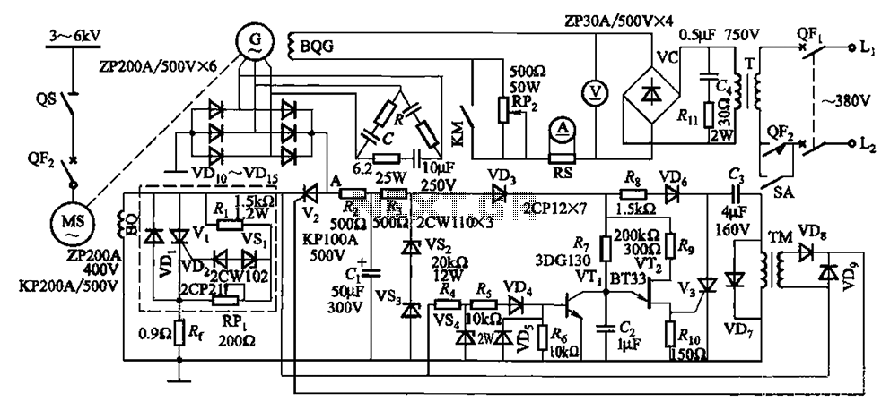
The circuit depicted in Figure 16-105 illustrates a synchronous motor. The components include BQ, which represents its field winding, and G, which denotes the AC excitation for the motor. The notation BQG indicates the field winding, with an empty...

This design outlines a simple wideband output amplifier suitable for use as a 50-ohm transmission line driver. The circuit is constructed using the CA3140 operational amplifier. When utilized alongside the function generator and sine wave shaper circuits, it delivers...
The power used for realignment is considered a loss in the context of the overall circuit. Due to the hysteresis loss in the saturable-core reactor, the power gain is relatively low. Adding a rectifier to the load circuit can...

The circuit is designed to connect in parallel with a telephone, displaying the dialed number using DTMF (Dual Tone Multi-Frequency) signaling. It can also show the number dialed from the receiving party's phone, making it useful for capturing numbers...
The circuit involves powering an LED using a 3V CR2032 battery, with the intention of extending battery life by making the LED blink rather than remain continuously on. A 555 timer is considered, utilizing large value resistors in the...

Figure 1-30 illustrates an example of an output capacitor-less (OCL) power amplifier circuit, which can be analyzed as follows: In this circuit, transistors VTi and VTz form a single-ended input and a differential input single-ended output amplifier configuration. The...