
Driving a Bipolar Stepper Motor with Arduino and ULN2803AG
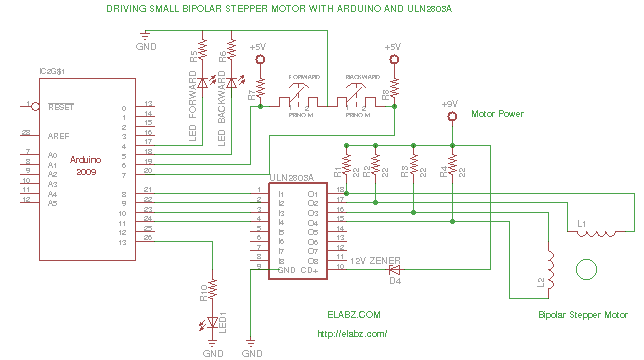
The circuit utilizes the ULN2803AG Darlington transistor array to drive a 4-wire bipolar stepper motor, which is characterized by its two winding pairs. The ULN2803AG features eight Darlington pairs, allowing for the control of two bipolar stepper motors simultaneously. The motor's windings are connected to the outputs of the ULN2803AG, while the inputs are connected to the Arduino pins, which send control signals.
The resistors used in this circuit are essential for floating the voltage of the windings. When the Arduino sends a HIGH signal to the corresponding pins of the ULN2803AG, it activates the respective Darlington pairs, allowing current to flow through the motor windings. By alternating the signals sent to the motor, the rotor can be made to turn in either direction. The use of 22 Ohm resistors, in this case, is a workaround to provide the necessary voltage levels across the windings; however, care must be taken regarding the power rating of the resistors to prevent overheating.
The Arduino sketch is designed to handle the logic required for driving the motor effectively. It defines pin numbers for various buttons and LEDs, allowing for user input to control the motor's direction and movement. The control logic ensures that the motor operates smoothly, taking into account the necessary HIGH/LOW states to prevent unnecessary power draw when the windings are disabled.
In summary, this circuit demonstrates a creative approach to utilizing the ULN2803AG to drive bipolar stepper motors salvaged from DVD-RW drives, providing a low-cost solution for hobbyists interested in motor control applications.While I`m getting ready to rip open some 10+ broken DVD-RW drives coming to me from an eBay seller, I though it would be great to have a testbed for the bipolar stepper motors I will harvest from those. I have a bunch of ULN2803AG Eight Darlington Transistor Arrays with Common Emitters left from past projects and these can sink (but unfortunately
not source) peak loads of 600mA (500mA continuous) and are well suited for power application like driving small motors. However, there is a problem with 4-wire bipolar stepper motors: they don`t have the common points of windings wired to the outside which would be needed for providing the motors with power.
See the ULN2003 datasheet for more information about the IC: ULN2801, 2802, 2803, 2804 and 2805 Darlington Array datasheet Still, it looked to me that it would still be possible to make a small bipolar stepper work by floating the voltage using some 22 Ohm resistors to the motor supply voltage (motor you see on the video has 18 Ohm windings, so this was the closest resistor value). At first I attempted to use for the motor voltage the same +5V supplied by Arduino but because of the floating middle point the max voltage across each winding was only 1.
7V and that was not enough to move the rotor. When the motor supply voltage was increased to +9V (the 9V battery on the picture), things started working. There is still only 4V across each winding at any time it`s energized but it looks enough to make the linear slide move with some force which I hope will be enough for carrying the laser diode housing.
Here is the schematic of the whole setup and below is the Arduino sketch. Please note that the resistors needed to be at least 1/4W rated but I did not have the 22 Ohm needed for the project and used 1/8W ones. They did get noticeably hot, so it`s not the way to do it in real life. Additionally, a better way to drive a 4-wire bipolar motor would be to use the quad half-H ICs like SN754410 (on which Arduino`s official bipolar instructions are based) but I thought many hobbyists would appreciate a possibility to make things run using a simpler hookup that ULN chips allow.
Also, one $0. 60 ULN2803AG chip can actually drive two motors, so it`s pretty much the cheapest way to drive your 4-way bipolar stepper. Please note that another common Darlington Array IC, ULN2003A (similarly priced) has 7 arrays instead of 8 and therefore can only be used to drive one stepper motor per IC.
Driving your 4-wire bipolar stepper via a ULN2803AG is not efficient because you`re wasting pretty much the same amount of energy on heating the resistors that float the median voltage point as you`re using for rotating the motor`s rotor but if efficiency is not your immediate concern, you can use this simple hookup with a little bit of programming that takes into consideration the different HIGH/LOW levels needed to drive the motor if hooked up this way. When 1 is HIGH and 2 is HIGH, the voltage across winding #1 is considered zero or winding disabled. This is basically done to conserve motor supply power. It works in exact same way as more logical LOW-LOW but LOW-LOW will draw current through the respective resistors simply wasteful.
// Driving a bipolar stepper motor with Arduino and a ULN2803 // Octal High Voltage High Current Darlington Transistor Array // This example code is in the public domain. Based on several // Arduino code samples // // constants won`t change. They`re used here to // set pin numbers: const int buttonPin = 2; // the number of the misc. pushbutton pin const int buttonForwardPin = 6; // the number of the misc. pushbutton pin const int buttonBackwardPin = 7; // the number of the misc. pushbutton pin const int ledPin = 13; // the number of the forward LED pin const int ledForwardPin = 4; // the number of the forward LED pin const int ledBackwardPin = 5; // the number of the backward LED pin const int motorPin1 =8; const int moto
🔗 External reference
Related Circuits
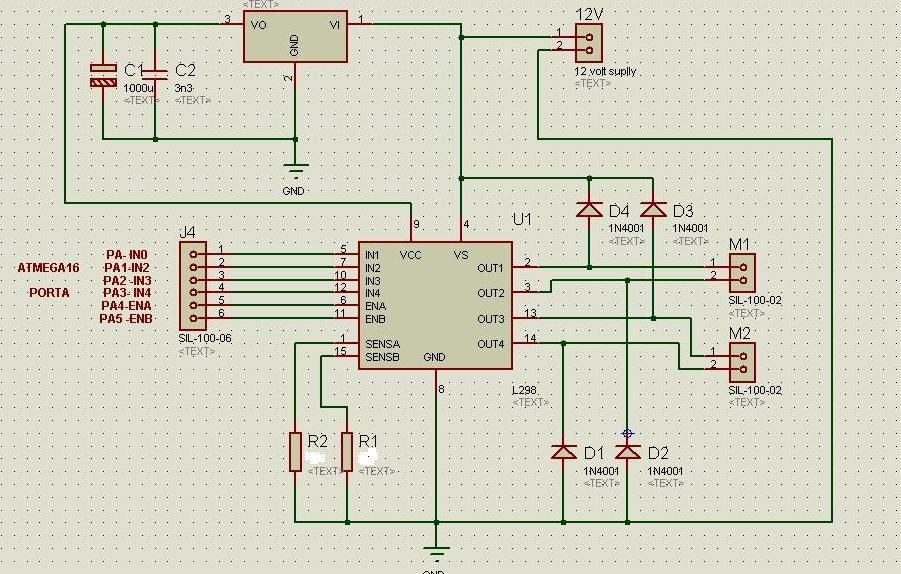
The circuit diagram includes M1 connected to Coil A of a stepper motor and M2 connected to Coil B of the stepper motor. Resistors R1 and R2 are 1 Ohm resistors used for current limiting. The circuit design involves a...

A three-phase electric motor overcurrent protection circuit. This example circuit utilizes a transformer to monitor the current, ensuring that the currents in the three-phase motor do not exceed normal operating levels. When the current exceeds the set threshold, the...
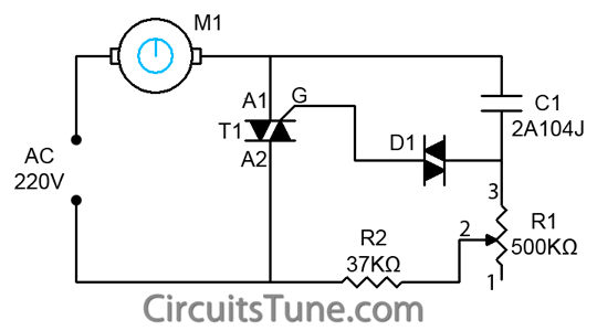
This is a simple ceiling fan regulator circuit diagram used to control the speed of a ceiling fan. In other words, it is an AC motor speed controller circuit that regulates the speed of an AC motor (ceiling fan)....
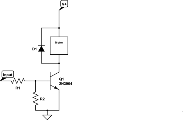
Control a small 5V motor using an external power supply by triggering a transistor with an Arduino. The transistor in use is an NPN type, specifically the 2N3904. To control a small 5V motor using an Arduino and an NPN...
This page is browser-friendly. To enhance readability, adjust your browser window to be narrower than the full screen. The page consists of two parts: the first part features a basic program demonstrating the RFID reader's functionality, while the second...

An AI comparator input is connected to a reference resistor (Rl). When the output reaches a specified level, known as VREP (absolute value), the output also stabilizes at this level. The outputs Ai and As are connected to an...