
dry model 1 isca tracker
This handmade prototype serves as a valuable tool for researchers exploring magnetic-field models in tracker systems. The design's flexibility, achieved through the use of standard components and software-driven functionalities, allows for extensive experimentation while minimizing hardware complexity. The integration of off-the-shelf coils and readily available microcontroller technology facilitates rapid prototyping and iteration, enabling researchers to focus on refining their magnetic-field models rather than dealing with the intricacies of custom hardware design. The use of classic construction techniques, such as hand-wiring on a copper ground plane, not only simplifies the assembly process but also enhances electromagnetic performance by reducing noise and interference.
The choice of the CY7C68013A microcontroller, coupled with the 8051 assembler language, allows for efficient processing and control of the sinewave generator, while the ADC evaluation board's architecture ensures accurate data acquisition from the telecoils. The provision for standalone operation of the ADC evaluation board further enhances the prototype's versatility, allowing it to function independently of a computer setup. This capability, along with the simultaneous measurement of currents and voltages, ensures that the tracker can maintain high accuracy in dynamic conditions, which is crucial for effective magnetic-field modeling.
Overall, this prototype not only demonstrates the basic principles of a tracker system but also serves as a foundation for future enhancements and innovations in the field of magnetic-field modeling. By providing a clear pathway for experimentation and development, it encourages further exploration and refinement of tracker technologies.This is a handmade prototype research project, intended to demonstrate what goes into a tracker and to facilitate developing tracker-related magnetic-field models. This is not a product. Functions needed in a product but not needed to explore field model performance (such as characterization-data memories on the coil assemblies, a calibration coil
in the receiver coil assembly, and fast digital data transfer) are not included. Pete used a combination of old and new parts, avoiding custom components. In particular, the coils are off-the-shelf parts and do not have to be custom-wound. The intent is that the design will inspire improved designs, rather than being exactly copied. To minimize hardware complexity (in particular, to eliminate the need for a field-programmable gate array, FPGA), and to ease experimentation, everything that can be done in software in the computer, is done in software in the computer. The programs for the Cypress Semiconductor CY7C68013A USB microcontroller are written in 8051 assembler language, and cross-compiled on the host computer using SDCC 2.
9. 0 into Intel hexadecimal format files for loading and running on the target CY7C68013A. The sinewave generator, DACs, and drivers are built on one copper-clad board using the classic amateur-radio ugly construction technique: hand-wired parts on a solid copper ground plane. C program dry0184. c, which compiles to executable dry0184, calculates the sinewave tables and outputs in Intel hexadecimal format without an end-of-file record.
The CY7C68013A assembler code dry0278. asm, which assembles into executable dry0278. ihx, copies the sinewave tables from the SRAM in the CY7C68013A into the SRAM in the sinewave generator. C program dry0277. c, which compiles to executable dry0277, loads an Intel hexadecimal format file onto the target CY7C68013A, and starts the CY7C68013A running.
The difference is that a line is terminated with a newline (which may itself be one or two characters), whereas a record may or may not be so terminated. Instead, the end of the record is determined by counting characters from the start-of-record colon character.
Once a record has ended, the Intel hex format allows any characters (except a colon) between records. Each of the three drivers uses a Texas Instruments (formerly National Semiconductor) LM384 five-watt audio power amplifier operating from +19 V to + 25 V Vcc supply.
A 2200 uF 35 V electrolytic capacitor at the lower right corner of the board provides bulk filtering for the driver Vcc rail. The rotary switch on the front panel selects one of the three driver MONITOR signals to drive a small output transformer and speaker.
This is useful for checking that the firmware correctly loaded and started the sinewave generator. The receiver comprises three Sonion T 20 AG telecoils hot-glued to be roughly orthogonal and roughly colocated. The photo shows one coil is tilted from orthogonal. The CS5368 Product Data Sheet, and CDB5364 Evaluation Board Data Sheet, were both downloadable from on June second, 2012.
The ADC evaluation board includes single-ended gain-of-two preamps for each of the eight ADCs. The preamps are driven directly by the receiver coils and by the one-ohm transmitter current-sense resistors, as shown in the block diagram. The currents and voltages are all measured simultaneously, so dynamic accuracy of the tracker will be as good as static accuracy.
Also, it does not matter when a 2047-ADC-sample measurement interval begins. The unused DAC output and the unused ADC input, could be used to add an electronics-calibration coil to the receiver. This would make the coil characterization independent of the gains in the electronics. The ADC evaluation board is jumpered to run standalone (without using computer setup interface) as in dry0537.
txt. The ADCs run at 48 kilosamples per second, providing buffered versions of the CS5368 clock and serial data output 🔗 External reference
Related Circuits
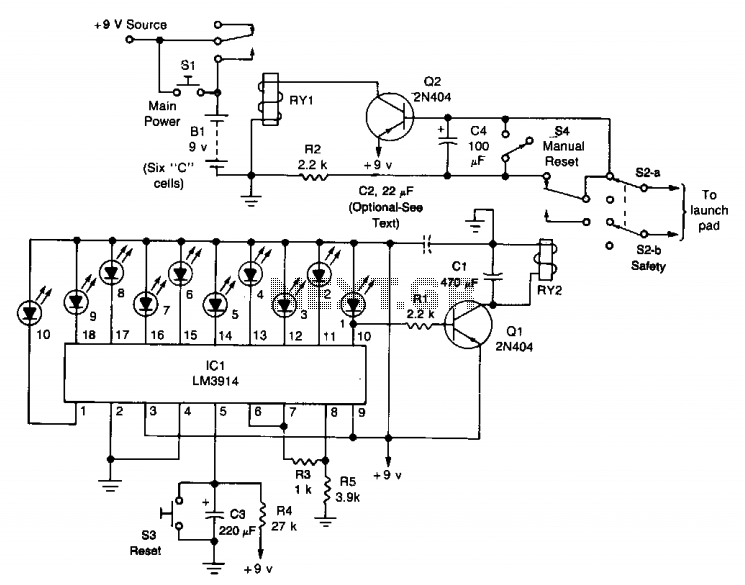
The circuit comprises a launch timer and an automatic-off timer. Upon applying power to the integrated circuit (IC), the countdown LED sequence activates until all LEDs are illuminated. When the last LED (LED1) is fully lit, transistor Q1 enters...
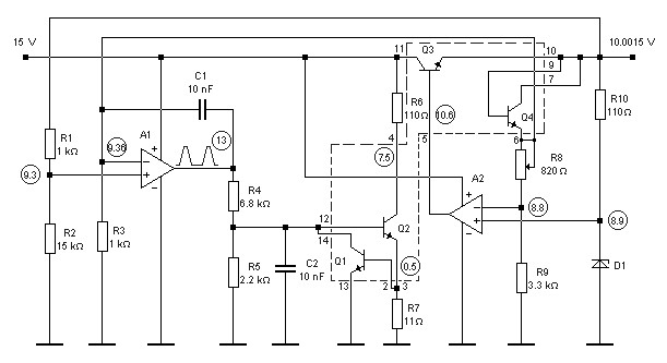
10V high-stability voltage source model power supply. Refer to the specified page for an explanation regarding the associated circuit diagram. The 10V high-stability voltage source is designed to provide a reliable and consistent output voltage, making it suitable for various electronic...
The LED arrangement in the LM339 circuit consists of two rows of three LEDs, with each LED connected in parallel. The two rows are connected in parallel but with reversed polarity. The sensor array is composed of three west-facing...
It was designed for use on a The London Model Railroad Group's large O scale layout located at London, Ontario, Canada. The prime requirements for the club throttles were that they be rugged, reliable and produce as little heat...
The following circuit illustrates photovoltaic light sensors in a solar tracker. Features include accuracy, low cost, simplicity, and a single-axis electronic design. The photovoltaic light sensor circuit is designed to optimize the alignment of solar panels with respect to the...
There are two independent modeling light circuits for the P2000D, one for each of the two channels. The modeling light circuit is completely separate from the high voltage strobe circuitry, even featuring its own On/Off switch. Therefore, the functionality...