
dual LED flasher
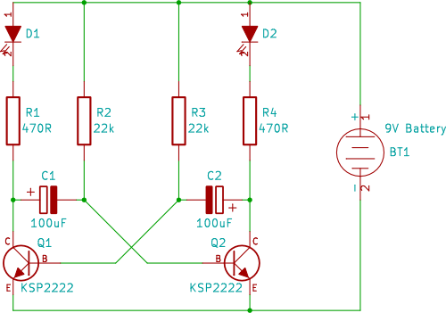
This circuit utilizes two NPN transistors configured in a flip-flop arrangement, which allows for the alternating flashing of two light-emitting diodes (LEDs). The basic operation relies on the transistors switching on and off in a complementary manner, creating a visual effect of the LEDs blinking alternately.
The circuit can be constructed on a breadboard for ease of assembly and testing. It typically includes the following components: two NPN transistors, two LEDs of different colors for visual distinction, resistors to limit the current through the LEDs and to control the base current of the transistors, and a power supply, usually a 9V battery or a regulated DC source.
The first transistor is connected to the base of the second transistor through a resistor, while the collector of the first transistor is connected to the anode of the first LED. The cathode of the first LED connects to ground. Similarly, the second transistor's collector connects to the anode of the second LED, which also connects to ground through its cathode.
When the circuit is powered on, one transistor initially turns on, allowing current to flow through its associated LED, causing it to light up. This action simultaneously turns off the other transistor, which extinguishes the second LED. As the first transistor turns off due to the lack of base current, the second transistor turns on, allowing the second LED to light up. This process continues to alternate, creating a flashing effect.
To ensure proper operation, the resistor values must be chosen carefully. Typical values for the base resistors can range from 1kΩ to 10kΩ, while the LED current-limiting resistors are often around 220Ω to 470Ω, depending on the LED specifications. This simple yet effective circuit serves as an excellent introduction to basic transistor operation and LED control for beginners in electronics.A two transistor circuit that flashes two LEDs on and off alternately. This tutorial shows beginners in electronics how to build the easy circuit on breadboard.. 🔗 External reference
Related Circuits
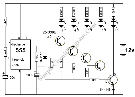
The circuit below demonstrates how to animate a bike turning signal using LEDs. The bike turning signal will blink sequentially from the right side (D1) to the left side (D5). This circuit utilizes a series of light-emitting diodes (LEDs) arranged...

A dual-tone model train horn/sound generator/simulator circuit can be created using two NE 555 timers connected in cascade. However, the circuit diagram presented is designed with the NE 556 integrated circuit, which essentially comprises two 555 timers in a...
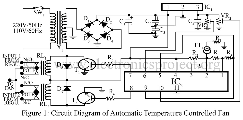
An automatic temperature-controlled fan regulates the fan speed based on temperature variations using the temperature transducer AD590 and an op-amp LM324 circuit diagram. The automatic temperature-controlled fan circuit utilizes the AD590 temperature transducer, which provides an output voltage that is...
These are small lights with a stake on the bottom that can be inserted into the ground along driveways or sidewalks, featuring a solar panel on top. The solar cell charges a AA NiCd battery during the day, and...
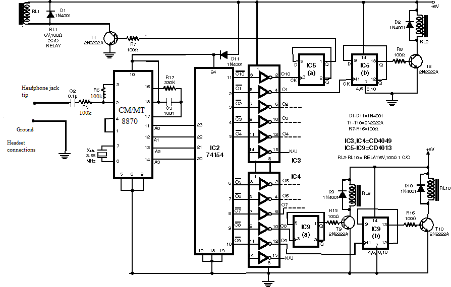
Have you ever imagined controlling your home appliances using your cell phone? Numerous circuits exist for this application, typically utilizing a telephone. This circuit has been modified and redesigned for compatibility with a standard cell phone headphone jack. To...
When constructing a stereo amplifier or if one is already owned, it is beneficial to incorporate this circuit. The entire setup is based on the IC4017, with its clock input connected through a BC107 transistor. The IC4017 functions as...
Warning: include(partials/cookie-banner.php): Failed to open stream: Permission denied in /var/www/html/nextgr/view-circuit.php on line 713
Warning: include(): Failed opening 'partials/cookie-banner.php' for inclusion (include_path='.:/usr/share/php') in /var/www/html/nextgr/view-circuit.php on line 713