
Low-distortion audio limiter circuit diagram
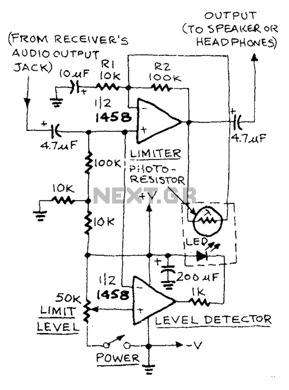
The AUD.LIMITER circuit is designed to regulate audio signal levels effectively, preventing distortion and ensuring consistent output. The circuit utilizes an operational amplifier configured in a comparator mode, which monitors the input signal against a reference voltage set by the trim potentiometer. The operational amplifier's output drives an LED, providing a visual indication of the limiting action.
In terms of operation, the circuit begins with an audio signal being fed into the non-inverting input of the operational amplifier. The trim potentiometer allows the user to set a threshold level, which is used as a reference voltage. When the audio signal exceeds this threshold, the output of the operational amplifier switches to a high state, illuminating the LED. This visual feedback is crucial for users to understand when the signal is being limited.
The light-sensitive resistor, also known as a photoresistor, plays a critical role in the feedback loop of the circuit. As the LED lights up, the resistance of the photoresistor decreases, which increases the gain of the operational amplifier limiter. This action helps to attenuate the audio signal, preventing it from exceeding the set limit and thereby protecting subsequent stages of the audio system from potential damage due to overdriving.
When the audio signal drops below the threshold, the LED turns off, and the resistance of the photoresistor increases. This change reduces the gain of the operational amplifier back to its normal operating levels, allowing the audio signal to pass through without additional attenuation. The resistors R1 and R2 are critical in establishing the gain of the operational amplifier in its normal state, ensuring that the circuit maintains the desired audio fidelity while providing effective limiting.
Overall, the AUD.LIMITER circuit is a valuable tool for audio engineers and technicians, providing a reliable means of controlling signal levels and preventing distortion in audio applications. Its design emphasizes simplicity and effectiveness, making it a practical choice for various audio processing tasks.AUD.LIMITER The level can limit level trim potentiometer to adjust. If you exceed the level of the potentiometer, the output from the half of the operational amplifier (as a co mparator) will limit detector LED lights, so light-sensitive resistor decreases rapidly. While the other half of the gain of the operational amplifier limiter will increase. When the signal falls below a desired limit level, the LED goes out, the photosensitive resistor increases limiter gain operational amplifier is reduced to normal levels, the combination of resistors R1 and R2 determine the gain of normal levels.
Related Circuits
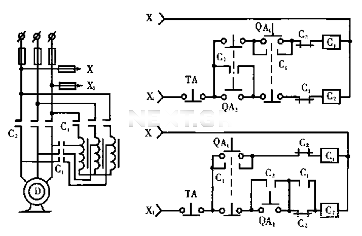
The circuit operates with relevant components highlighted in the manual's draw mode. Figure A presents a circuit schematic, while Figure B illustrates a typical conventional secondary circuit layout. Figure E showcases an improved secondary circuit schematic diagram that incorporates...
The circuit utilizes an infrared (IR) receiver chip to capture IR signals from a remote control. This chip features a bandpass filter and a demodulator, resulting in a logic-level output. The controller section is based on a standard 8051...
This project involves an automatic street light or lamp circuit designed to activate outdoor lights, such as garden lamps and night lights, automatically at sunset and turn them off at sunrise. The circuit is sensitive and versatile, capable of...
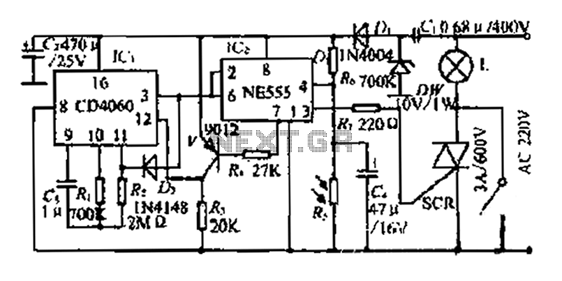
A photosensitive daytime electricity circuit utilizes a very small positive voltage. It features a 555 timer IC with four pins, including a reset pin that operates at low voltage. The circuit includes a bidirectional thyristor (iSCR) that controls lighting,...
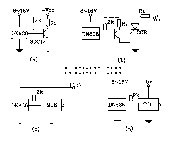
Figures (A), (B), (C), and (D) illustrate outputs that can directly drive transistors, thyristors, relays, CMOS circuits, and TTL circuits. The described figures depict various output configurations capable of interfacing with different electronic components. Each output is designed to provide...
The SE555/NE555 timer was first introduced by the Signetics Corporation around 1971. Pin connections and functions are as follows: Pin 1 (Ground) - This pin serves as the ground or common pin, representing the most negative supply potential of...