
Easy Debugging Terminal
The Easy Debugging Terminal is designed to facilitate serial communication and data visualization through an LCD interface. The primary operational modes are determined by the configuration of jumper J1, enabling the user to switch between standard ASCII display and hexadecimal data viewing. The use of the PIC16F84 microcontroller allows for efficient control of the terminal's functionalities, including data input handling and LED management.
Input signals are routed through connector K1, which serves as the interface for serial data. The power supply options provide flexibility for various applications, accommodating both fixed and portable setups. The jumper J1 plays a crucial role in determining the mode, thus allowing for real-time data monitoring or debugging based on user requirements.
LED D3's functionality enhances the user experience by providing visual feedback, which can be especially beneficial in debugging scenarios. The option to control the backlight of the LCD display through a buffer circuit further improves visibility in low-light conditions. The variable resistor P1 offers a straightforward method for users to adjust display contrast, ensuring optimal readability.
The choice of a 16x2 or 16x1 LCD module allows for versatility in design, accommodating different user preferences and project specifications. The use of a universal PCB simplifies the construction process, enabling easy integration of the LCD module and ensuring a compact form factor.
Software development for the terminal utilizes the PIC C compiler, with source code and hex files provided for both LCD module types. This modular approach allows users to adapt the firmware to suit their specific needs, fostering a user-friendly environment for modifications. The recommended delays after command transmissions and power-up ensure reliable operation, preventing potential timing issues that could disrupt data communication.
Overall, the Easy Debugging Terminal represents a robust solution for serial data visualization, combining flexible hardware design with adaptable software capabilities.This LCD terminal provide two modes of operation by selecting jumper J1. When J1 is open the terminal operate as a normal ascii display terminal, when J1 is closed the terminal displays the input serial data in hexadecimal format. This mode is useful for viewing raw data from the serial port output. Figure 1 shows the circuit diagram of the Easy D ebugging Terminal. IC U2 a PIC16F84 micro controller is used to control the operation of the terminal. Input signal is applied to connector K1. The circuit can be powered either by 9V dc adapter or by using a 9V battery. Jumper J1 select the operating mode of the terminal, J1 open for ascii terminal mode, closed for hexdecimal display mode. LED D3 can be controlled by software command provided in ascii mode. This LED output can also be used (with buffer circuit) to control the backlight of the LED backlit display.
Variable P1 is used to adjust the contrast of the display. The circuit uses a 16x2 line LCD module, while a 16x1 module can also be used. The prototype board may be built using universal PCB having the same size as of LCD module so that LCD module can be mounted on top of universal PCB using SIP connectors. The software of the project was developed using PIC C compiler from CCS. The source code of the project is available in the file Lcd_Dtm. c, there are two types of hex files are available Lcd_Dtm. hex is used for 16x2 lines LCD module, while Lcd1. hex is used for 16x1 line LCD module. The user can easily modify the source file for other types of Lcd modules. It is better to use a delay of 100 usec after sending commands to the terminal except for the clear display command which will require a minimum delay of 2 msec.
Also after power up a delay of 120 msec is required before sending the commands or data to the terminal. 🔗 External reference
Related Circuits
The TVT-MOBI-2 will initially display a static image and will not respond to data from its serial interface, except for one function. The internal clock can be set by providing a date and time value, allowing it to calculate...
Easy Joule Thief Soldering Kit from MakersBox on Tindie The Easy Joule Thief Soldering Kit is designed for educational purposes, allowing users to learn about basic electronics through hands-on experience. This kit includes all necessary components to assemble a Joule...
An EEPROM is a type of non-volatile memory, which means it is used for permanently storing digital data without any power supply. EEPROM stands for Electrically Erasable Programmable Read-Only Memory. The advantage of this type of ROM is that...

I have been measuring V_A = 15, which appears to be incorrect. Additionally, I believe V+ is equal to 0 since the node below the 3-ohm resistor is grounded. Assistance is needed to begin solving this. Initially, I set...
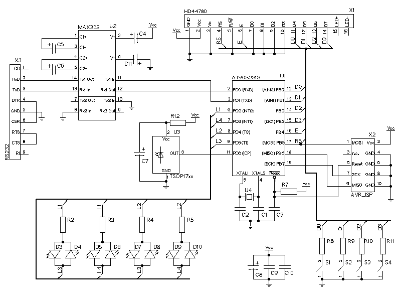
The LCD display is represented by the connector X1. It has a HD44780 compatible LCD controller and is using the 4-bit interface to send data to the LCD controller. The LEDs are multiplexed. It is possible to connect 12...
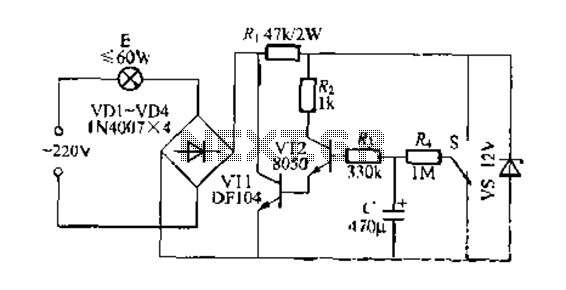
This circuit is a gradual clear/fade switch for a two-wire connection, designed for simple installation. It activates the lights as needed by turning the switch dial upward. A positive supply of 2V is provided through resistor R. The capacitor...