
Electric Furnace Schematic Wiring Diagram
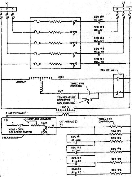
The circuit diagram in question illustrates a heating element controlled by a series of switches, including a Normally Open (N.O.) switch. The main identifiers for these switches, M1 and M2, indicate their role in the sequencer system. The circuit's operation hinges on the proper application of 240 volts to the heating element, which can be verified through direct voltage testing at the element's wiring connections. This procedure is essential for diagnosing heating issues reported by users.
In troubleshooting, if the voltmeter indicates no voltage (0 volts), it is critical to confirm the integrity of the heating element itself. This can be achieved by measuring its resistance with an ohmmeter, ensuring that the element is functional. If the element's resistance is within acceptable limits, attention should turn to the series switches for potential faults.
The process of checking for Potential Voltage involves examining the fuse connected to the circuit. Since the fuse acts as a switch that opens under fault conditions, measuring voltage across its terminals will provide insight into the circuit's operational status. The left terminal connects back to the L1 side of the line, while the right terminal connects to the L2 side, confirming that the entire circuit path, including the heating element and switches, must be intact to obtain a valid Potential Voltage reading.
This methodical approach to testing and troubleshooting ensures that all components in the circuit are evaluated, thereby facilitating the identification of the root cause of any operational issues. By systematically checking both Applied Voltage and Potential Voltage, technicians can effectively diagnose and resolve heating problems in the system.On this diagram, you can easilily locate test points related to Applied Voltage and Potential Voltage. For example, isolating one of the heating elements, we can see that there is an N. O. (Normally Open) switch shown wired in series with it, and the identifiers on this particular switch are M1 and M2 (M, meaning Main set of contacts on a sequencer SEQ #1 in this case .
), and in a sitution in which a technician would want to find out if this circuit is working like it should, a smple test for Applied Voltage would be a good place to start. Checking with a voltmeter directly at the wiring connections for the heating element to find out if the required 240-volts was being applied or not would allow us to begin to evaluate this particular circuit in the event we were troubleshooting a situation in which the customer was complaining that the unit wasn`t heating properly.
And, depending on the results of that test, we would be able to find out if the element itself, or the switches wired in series with it, could be a source of a problem. For the sake of creating a troubleshooting scenario, let`s say that the answer to the question, Is there voltage applied to the element is no.
The reading we get with the meter is 0-volts, not the 240-volts that would allow the element to provide heat as long as it OK, meaning that it would have the proper resistance if we checked it with an ohmmeter. But . I digress. We`re not talking about using an ohmmeter to check resistance, we`re talking about doing a hot test with a voltmeter to determine which component in the circuit could be a source of the problem, so, back to the idea of Applied Voltage and Potential Voltage .
Once our first test showed no Applied Voltage, our next step would be to check the switches wired in series with the element ot see if they were doing what they were supposed to do, which introduces the idea of checking for Potential Voltage. Moving to the left of the element, there is a fuse. Checking directly at the terminals of this fuse would be implmenting a check for Potential Voltage because of a simple rule regarding a switch (which, is technically what a fuse is .
just a switch that only opens once). And that rule is, Voltage can be read across an open switch . If you trace from the left terminal connection of the fuse, you`ll go all the way back to the L1 side of the line. If you trace from the right terminal connection of the fuse, you go all the way back to the L2 side of the line, proving along the way that the element, the limit switch, and the fuse at #1 on the L2 terminal blockmust be in the condition I mentioned above, because if any of those conditions didn`t exist, we wouldn`t be able to get the Potential Voltage reading at our test points.
🔗 External reference
Related Circuits
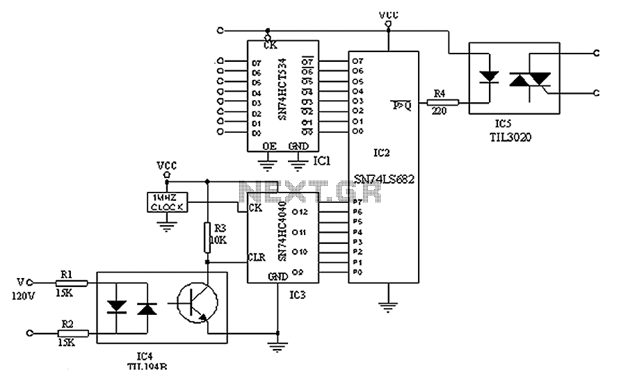
A simple digital circuit is presented that can be used to precisely control the AC power supply. This circuit does not include a digital-to-analog conversion component. In its application, effective control is established through a computer system that sends...
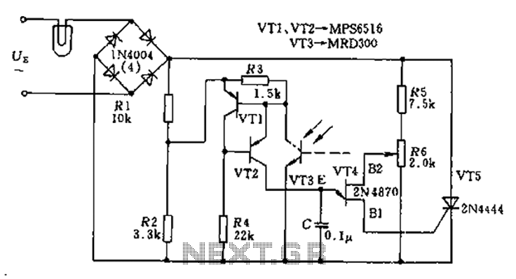
The circuit utilizes a thyristor-based AC automatic voltage regulator to stabilize the brightness of lamp L. A diagonal line connects the thyristor to the T5 bridge. The trigger pulse for the thyristor is generated by a single-junction transistor, VT4....

The circuit operates by processing an input signal through IC1-1 and a fourth-order low-pass filter, which provides a slope of 24 dB/octave with a cutoff frequency (fc) of 70 Hz and an amplification of 8.2 dB. The output from...
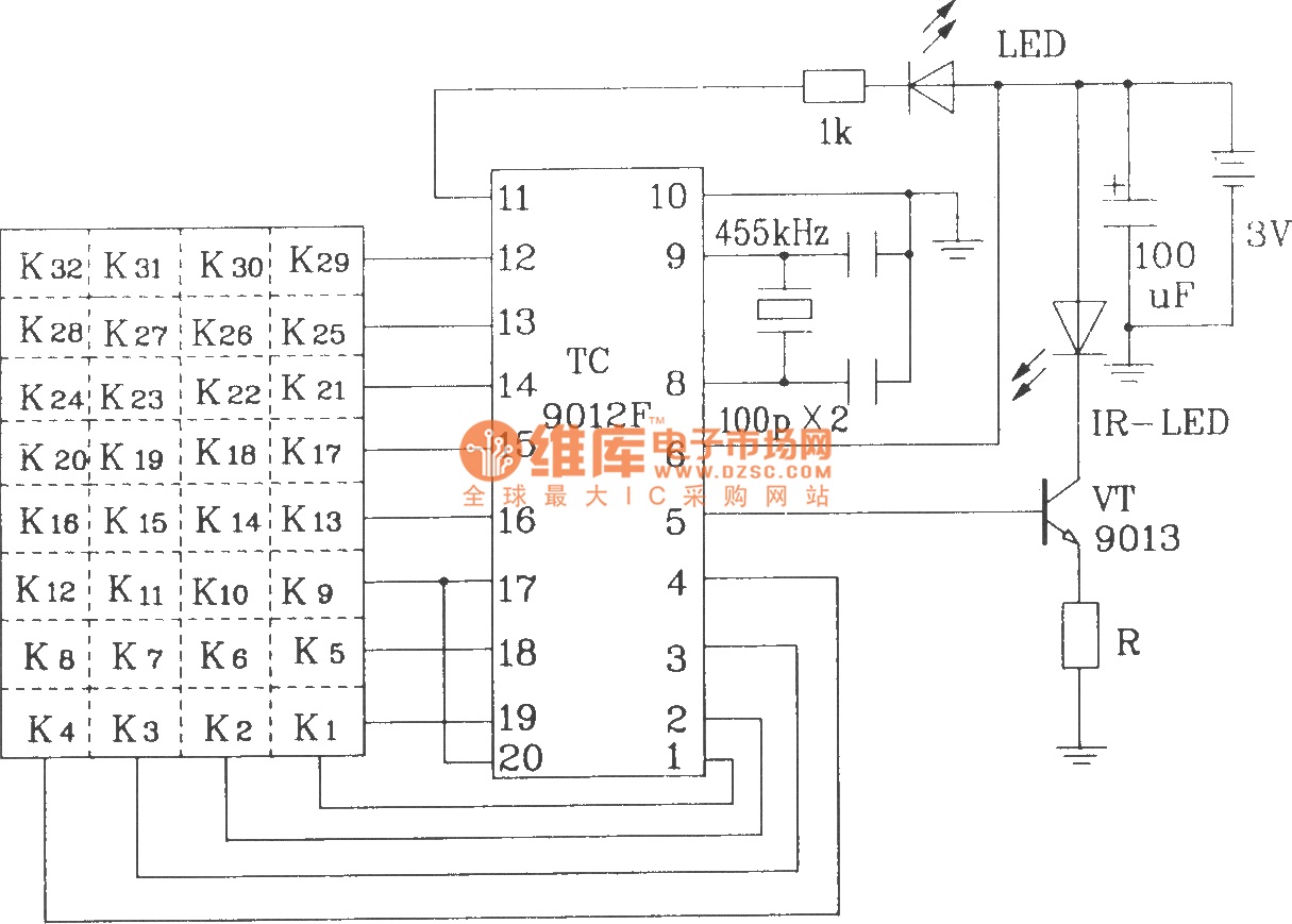
The TC9012 is a specialized off-screen remote control code transmitter. It incorporates an oscillator, divider timing generator, system code latch, data storage, key scan input, key scan output, and carrier control and output units. The internal 8-bit system code...
Circuit diagram of a modulator circuit in a transmitter and receiver of amplitude modulation. The modulator circuit in an amplitude modulation (AM) transmitter and receiver plays a crucial role in the process of encoding information onto a carrier wave. In...

This is a simple and low-cost NiCd and NiMH battery charger. The schematic diagram indicates that the charging current (I) should be set to 1/10 of the battery's rated capacity. For instance, if the battery has a rated capacity...
Warning: include(partials/cookie-banner.php): Failed to open stream: Permission denied in /var/www/html/nextgr/view-circuit.php on line 713
Warning: include(): Failed opening 'partials/cookie-banner.php' for inclusion (include_path='.:/usr/share/php') in /var/www/html/nextgr/view-circuit.php on line 713