
Electronic Lock
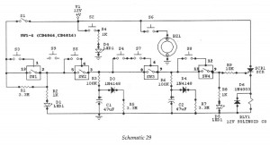
The electronic code lock utilizes a digital integrated circuit (IC) to manage access control through a coded input mechanism. This type of lock typically consists of a keypad for user input, a microcontroller to process the entered code, and an actuator to physically unlock the mechanism when the correct code is entered.
The system operates by first prompting the user to enter a predefined code via the keypad. The microcontroller continuously monitors the input and compares it against a stored code in its memory. If the entered code matches the stored code, the microcontroller sends a signal to the actuator, which can be a solenoid or a motor, to disengage the locking mechanism.
In terms of power supply, the circuit usually operates on a low-voltage DC source, often ranging from 5V to 12V, ensuring safety and compatibility with common electronic components. Additionally, the design may include features such as LED indicators to provide visual feedback on the lock's status, and a buzzer to alert the user of incorrect entries or successful unlocks.
For enhanced security, some electronic locks may implement features such as temporary lockout after a certain number of incorrect attempts, or the ability to change the access code, thereby allowing for customizable security measures.
The complexity of the circuit can vary, with some designs incorporating additional functionalities such as remote access control, integration with home automation systems, or even biometric sensors for added security. Overall, the electronic code lock represents a sophisticated application of digital electronics, combining user interface design with secure access control technologies.Digital IC, Electronic Lock , Here is an electronic code lock, which can be used as a door latch or key for ignition, etc. Operation is fairly tricky and there lies the beauty of the ci. 🔗 External reference
Related Circuits
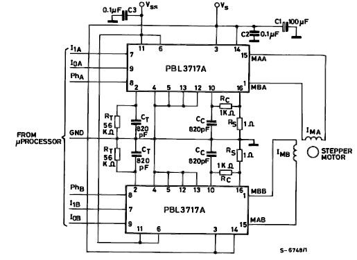
The PBL3717A stepper motor driver is a monolithic integrated circuit that controls and drives one phase of a bipolar stepper motor utilizing chopper control for phase current regulation. Current levels can be selected in three increments using two logic...
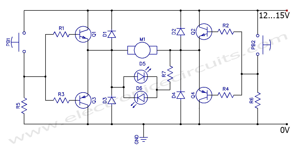
This circuit can control the direction of a DC motor, allowing it to operate in both clockwise and counterclockwise directions (forward and backward). The described circuit employs an H-bridge configuration, which is essential for reversing the polarity of the voltage...
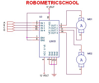
The electronic schematic of a DC motor driver using the L293D, as illustrated in Figure 2, enables the control of two DC motors continuously. It allows for one motor to rotate clockwise while the other rotates counterclockwise. Additionally, all...
This is a programmable clock timer circuit that uses individual LEDs to indicate hours and minutes. 12 LEDs can be arranged in a circle to represent the 12 hours of a clock face and an additional 12 LEDs can...
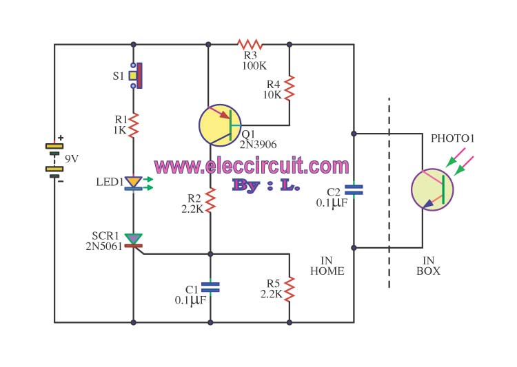
This is an integrated electronic mailbox circuit diagram designed for a front door. It activates when the door is opened. Additionally, when the cabinet photo detector is exposed to light, it will... The integrated electronic mailbox circuit is designed to...
A circuit is being designed to operate based on car locks, which receive a negative pulse to activate a latched relay, powering the ACC line that connects to a startup/shutdown controller. The current circuit configuration presents a challenge; to...