
Logic Probes
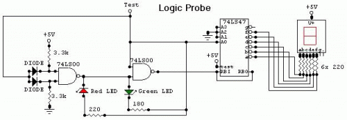
The Logic Probe circuit is designed to provide a simple and efficient means of determining the logic state in TTL (Transistor-Transistor Logic) circuits. It typically consists of a few key components: a voltage comparator, two light-emitting diodes (LEDs), and a resistor network.
The circuit operates by measuring the voltage at the test point through the "Test" wire. The voltage comparator compares the input voltage at this wire against preset thresholds that define the logic levels. For TTL circuits, the common thresholds are set to distinguish between Low, High, and Impedance states.
When the "Test" wire is connected to a node with a voltage below 2V, the comparator outputs a signal that activates the green LED, indicating a Low state. Conversely, if the voltage is between 3V and 5V, the comparator activates the red LED, indicating a High state. In the case where the wire is unconnected or floating, the comparator does not detect a valid voltage level, resulting in no LEDs being lit, which indicates an Impedance state.
The power supply for the Logic Probe is critical; it must match the Vcc of the circuit under test to ensure accurate readings. This is typically achieved through a simple connection to the circuit's power rails. The circuit is designed to be compact and portable, allowing for easy use in various testing scenarios.
Overall, the Logic Probe is an essential tool for engineers and technicians working with digital circuits, providing clear visual feedback on the state of logic signals without the need for complex equipment.This circuit is a Logic Probe. It indicates the logic state of the node of any TTL logic circuit. To do that, we have to supply the probe with the same power of the circuit that we want to analyse: same Vcc and same GND. To check the logic level, we must connect the "Test" wire of the probe to the desired node of the circuit that we want to check.
If the level is Low, the probe will display a "zero" (0) and only the green LED will be lighted. If the level is High, the probe will display a "one" (1) and only the red LED will be lighted. If the level is Impedance, the probe will display a nothing and no LED will be lighted. The logic level is "Low" when the "Test" wire is connected to the ground of the circuit (the voltage is between 0V and 2V). The logic level is "Impedance" when the "Test" wire is unconnected (it has no voltage or the voltage is between 2V and 3V).
The logic level is "High" when the "Test" wire is connected to the positive supply of the circuit (the voltage is between 3V and 5V). 🔗 External reference
Related Circuits
These two simple circuits provide zero voltage switching. They can be used with full wave bridges or in antiparallel to provide full wave control and are normally used to trigger power thyristors. If an input signal is present during...
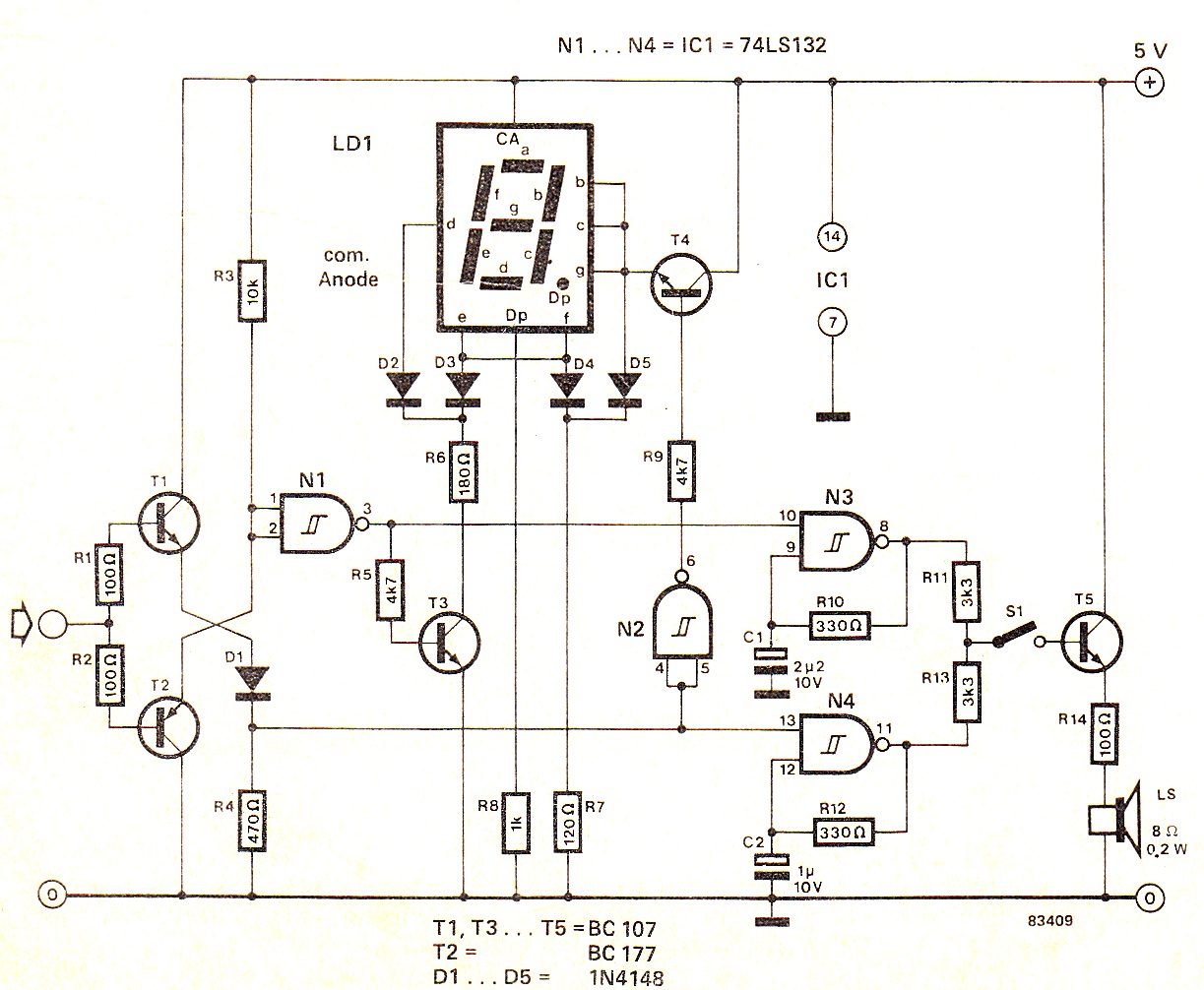
When the input signal is at logic high (1), the display indicates `H`, and the loudspeaker emits a note that is one octave higher than the low tone. The operation of the circuit can be observed in the circuit...
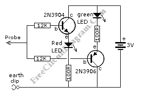
This is a simple logic probe circuit. A logic probe is used to determine if a point in a circuit has a high or low state when the circuit is in operation. The logic probe circuit is a fundamental tool...
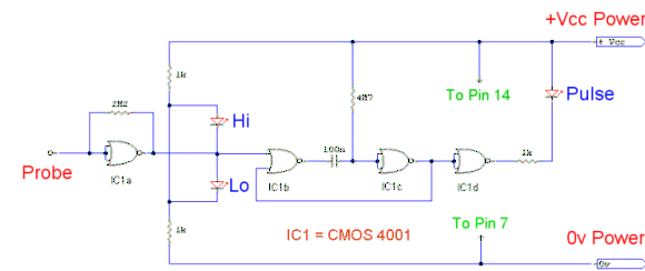
This logic probe utilizes a single CMOS integrated circuit (IC) to indicate three logic states: High, Low, and Pulsing. If the probe input is in a high impedance state, which occurs when it is not connected to a circuit,...
Invert a signal to drive FETs with rapid rise and fall times. It was suggested to use an inverter (not a chip) instead of logic chips, which are designed to be either fully ON or OFF. The individual has...
The tester provides an audible indication of the logic level of the signal presented to its input. A logic high is indicated by a high tone, a logic low is indicated by a low tone, and oscillation is indicated...