
Equalizer Circuit Operating on Three Bands
The tone control circuit serves as an essential component in audio processing systems, allowing for the modification of sound characteristics to enhance listening experiences. This circuit typically employs a combination of resistors, capacitors, and operational amplifiers to manipulate the frequency response of audio signals.
In a standard tone control circuit, three main adjustments are often available: bass, midrange, and treble. Each control adjusts the gain of specific frequency bands to either boost or cut their levels. The circuit can utilize a potentiometer for each control, enabling users to vary the resistance and thus alter the signal path.
For instance, a low-pass filter may be implemented for bass control, allowing low-frequency signals to pass while attenuating higher frequencies. Conversely, a high-pass filter may be used for treble control to permit high-frequency signals through while reducing lower frequencies. The midrange control can be achieved through a band-pass filter, which selectively enhances or diminishes mid-frequency signals.
The output stage of the tone control circuit typically connects to a power amplifier or directly to a speaker. Careful consideration of component values is crucial to ensure that the desired frequency response curves are achieved, which can be plotted using Bode plots for analysis.
Overall, the tone control circuit is an invaluable tool in audio applications, providing users with the ability to tailor sound output to their preferences and environmental conditions.The circuit was designed to illustrate the use of tone control circuit by which the audio signals are adjusted before being carried out to any output devi.. 🔗 External reference
Related Circuits
The protected section of track can be of any desired length and does not need to be equal on both sides of the crossing. The circuit operates bidirectionally and can be linked with other grade crossing circuits to provide...
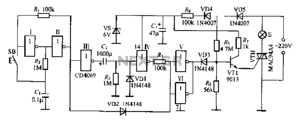
A delay lamp circuit is ideal for bedside tables, featuring a button (SB) that turns the light on and off. If the button is not pressed, the circuit maintains a delay before the light turns off. If the light...
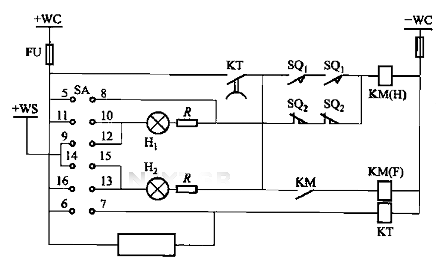
The BT9404 is a de-excitation type switch utilized with CJ4-S contactors and JT3-21/3-type electromagnetic relays. The control circuit is depicted in Figure 7-55. The KM contactors used are CJ4-S, while the time relay is the JT3-21/3. The SA component...
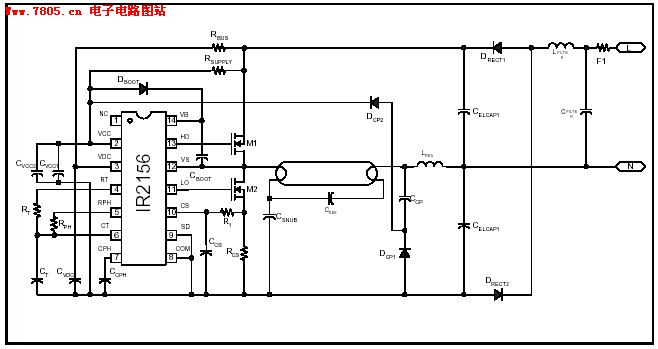
The IR2156 provides a cost-effective solution for fluorescent electronic ballasts. It integrates features such as lighting tube error protection and a programmable working frequency, which includes warm-up, lighting, and continuous operation of the ballast. The IR2156 is a highly integrated...
When the tank is empty, the wires within it are open-circuited, causing the 180K resistor to pull the switch low, resulting in the switch being open and the LEDs being OFF. As water begins to fill the tank, the...
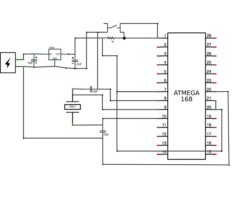
ATMega168 or ATMega328 microcontroller chip with Arduino bootloader (the one on your Arduino can be used temporarily) costs between $4.00 and $5.50. It is advisable to purchase an unbootloaded chip from Mouser for a lower price or a bootloaded...