
Fet curve tracer

The described circuit is designed to analyze the characteristics of Junction Field Effect Transistors (JFETs), specifically focusing on the relationship between the drain current (Id) and the gate voltage (Vg) for both P-channel and N-channel types. This analysis is crucial for understanding the operational behavior of JFETs within various electronic applications.
In the circuit, the drain current is monitored while maintaining a constant drain-source voltage (Vds). The gate voltage is varied to observe how it impacts the drain current. For N-channel JFETs, as the gate voltage is decreased (more negative), the depletion region widens, leading to a reduction in the channel conductivity, which in turn decreases the drain current. Conversely, for P-channel JFETs, increasing the gate voltage (more positive) results in a similar effect, reducing the drain current.
The circuit typically includes a power supply to provide the necessary Vds, a variable resistor or potentiometer to adjust the gate voltage, and an ammeter or current sensing resistor to measure the drain current. The output can be graphed to create a characteristic curve, illustrating the Id versus Vg relationship for both types of JFETs. This curve is essential for determining the operating region of the transistors and for designing circuits that utilize them effectively.
In summary, the circuit serves as a fundamental tool for studying the electrical characteristics of JFETs, aiding in the design and implementation of more complex electronic systems.The circuit displays drain current versus gate voltage for both P and N-channel JFETS at a constant drain voltge.
Related Circuits

A Field Effect Transistor (FET) is an amplifying device where the output current is influenced by the input voltage. The FET preamplifier described here is sensitive. The Field Effect Transistor (FET) operates by utilizing an electric field to control the...

Both utilized a pair of capsules from Neumann's K67 family, stacked vertically, with the upper capsule capable of rotating 270° relative to the lower one (presumably between -90° and +180°, similar to the USM 69). The capsule employed is...

This is a high-fidelity, high-quality audio amplifier circuit diagram. A pre-amplifier is not required. Component list: R1, R4 = 47K 1/4W resistors; R2 = 4.7K 1/4W resistor; R3 = 1.5K 1/4W resistor; R5 = 390Ω 1/4W resistor; R6 =...
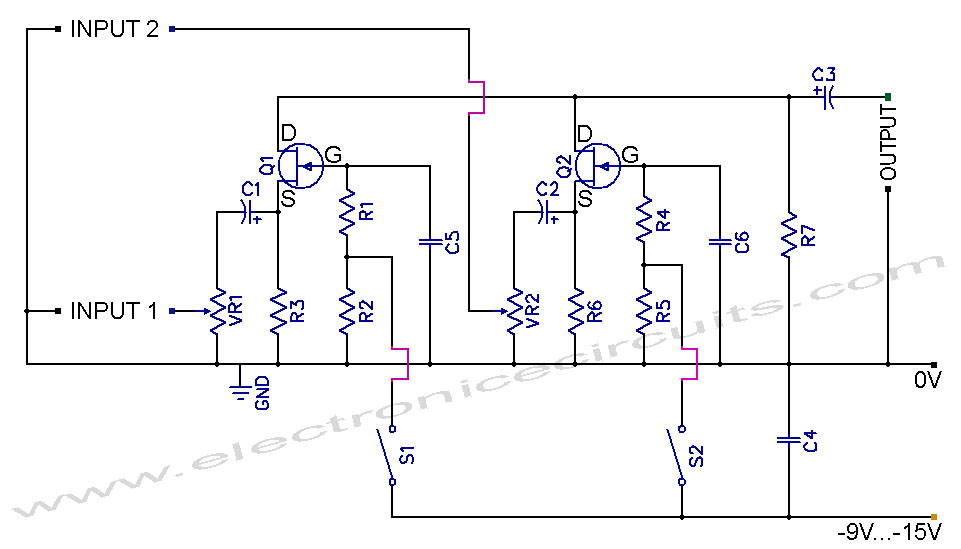
Instructions for building a FET audio mixer and switch circuit. The parts list includes: R1 - 1MΩ, R2 - 47kΩ, R3 - 47kΩ, R4 - 1MΩ, R5 - 47kΩ, R6 - 47kΩ, R7 - 47kΩ, VR1 - 50kΩ, VR2...
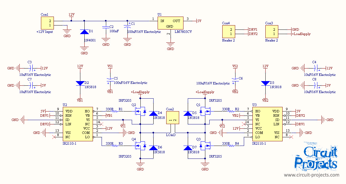
Assistance is required for a final year project involving the design of a grid-connected inverter. The focus is on developing a full bridge inverter circuit. The grid-connected inverter is a crucial component in renewable energy systems, particularly in solar photovoltaic...
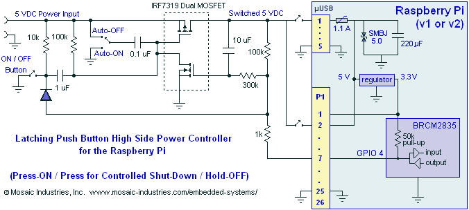
A momentary contact push button switch can be utilized to conveniently turn the Raspberry Pi (RPi) ON and OFF. Pressing the button will apply power to the micro USB header, maintaining power while the Raspberry Pi initializes and starts...