
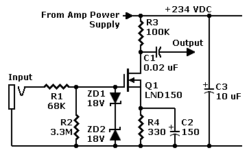
FET Preamp with LND150
When building the circuit, it is advisable not to skimp on board size unless space constraints dictate otherwise. A two-by-two or two-by-three inch board is suitable for this circuit. Bus wires should be run across the top and bottom of the board's backside, with the ends looped through the last two holes to protrude from the component side for easy connection to the power source. Off-board jumpers can be connected to push-in stakes, such as those made by Vector® (part T42-1/C), which are available from suppliers like Mouser. Components are mounted on the top side, with leads passing through to the back, where most wiring will be routed. The circuit should closely follow the schematic, with the power bus positioned at the top of the board. The FET should be mounted midway between the ground and power buses, and resistors should be tack soldered between the appropriate power bus and the FET.
The board can be mounted using standoff bushings, commonly found in hardware stores, and should be placed in a quiet, cool area within the amplifier cabinet. It can be secured to the cabinet wall or standoffs, ensuring that power lines remain short and the input is kept separate from the power transformer.
Prototype construction was initiated on June 7, 2010, with the active portion of the preamp breadboarded on a plugboard, utilizing an old Conar® tube power supply for B-plus voltage (234 volts derived from a divider post the 5U4 rectifier). A 330-ohm source resistor was identified as optimal after testing with 390 and 270-ohm resistors, yielding drain voltages close to the target of 117 volts. The 330-ohm resistor provided a drain voltage of 122 volts, accounting for source drop and the FET's internal resistance.
Optional capacitors C2 and C3 are included in the schematic, allowing for experimentation to customize the preamp's response to the power amplifier. Capacitor C2, acting as a bypass for the source resistor, enhances gain, particularly at higher frequencies, with its value based on those used in the Gibson® GA-1RT practice amp. Adjusting C2 can tailor the frequency response, increasing its value for more bass or decreasing it for more treble. Prior to adding C2, it is advisable to test the preamp without it to determine if additional gain is necessary. Capacitor C3 serves as an extra power supply filter, which may be required if excessive hum is detected, particularly in setups with long power lines.
The gate resistors can be modified without significantly impacting performance; for instance, a 75K or 47K resistor can be utilized for R1, while R2 can range from 100K to 10M. It is essential to remember that lower resistor values will impose a load on the input circuit (guitar), whereas higher values may introduce noise into the power supply.Above, the saturation region starts at the knees on the left. We`re interested in curves for negative gate voltages (depletion mode). Note that this device also operates in enhancement mode (with positive bias)! Flexibility. The construction method for this preamp is quite flexible. You can use point-to-point wiring with terminal strips, perfboard , or a PC board. I recommend perfboard, such as Vectorbord ®. Look for the type without copper traces. Use the general-purpose type with holes that are 0. 042-inches in diameter. These holes should have 0. 1-inch spacing. Building the circuit. Unless you must fit the circuit into a cramped space, don`t be stingy with the board. Be sure to allow for mounting space around the project. This circuit should then fit on a two-by-two or two-by-three inch board. Run bus wires across the top and bottom of the board`s backside. Loop the ends of the wire through the last two holes in the board. The loops should poke out the top or component side of the board. While testing, you can connect these loops to your power source. Connect off-board jumpers to push-in stakes. (Vector ® makes these stake terminals. I suggest part T42-1/C. Such hardware is available from Mouser. ) Components mount on the top, with leads poking through the holes to the back of the board. Most of the wiring runs across the back of the board. Otherwise, build the circuit as nearly a literal copy of the schematic. That is, the power bus becomes the top of the board. Mount the FET halfway between the ground and power buses. Tack solder resistors between either power bus and the FET as appropriate. You can mount the board on standoff bushings. Most hardware stores stock such bushings. Slip the tiny PC board into a quiet, cool corner of the amp cabinet. Mount the board on standoffs. Or screw it to a wall of the cabinet. Just keep the power lines short. Also, separate the input from your power transformer. Prototype. On June 7, 2010, I breadboarded the active part of this preamp on a plugboard. An old Conar ® tube power supply provided the B-plus power voltage. (The 234 volts comes off a divider after the supply`s 5U4 rectifier. ) Source Resistor. A 330-ohm source resistor (as in other circuits on the Web) seems to be the best value. I bracketed that by trying a 390 and a 270-ohm resistor (standard values). Each of these produces close to the desired drain voltage. The 390-ohm resistor gives me 130 volts, which seems too high. The 270 gives me 114 volts on the drain, the closest to my goal of 117. Yet I want to allow for the source drop and the FET`s internal resistance. Considering those voltage drops, I think that the 330-ohm resistor is the best choice. This resistor gives me 122 volts. Particular FETs and resistors vary. For best performance, your circuit might require a value different than 330 ohms. Capacitors. On the schematic, I`ve drawn in optional capacitors C2 and C3. Some experiments with and without these parts will help you to tailor the preamp to your power amp. Capacitor C2 is a source resistor bypass capacitor. This part will increase gain, especially for high frequencies. I base the value on capacitors that Gibson ® used in the GA-1RT practice amp. My value is proportional to the Gibson value. For more bass, you can increase the C2 value. For more treble, decrease the C2 value. Before you add C2, try out the preamp. You might not need the added gain. Capacitor C3 is an extra power supply filter. Again, try the amp without this capacitor. Do you hear any extra hum If the power lines are long, you might need this capacitor. Gate resistors. Without substantially affecting performance, you can change the values of the gate resistors. For example, you can use a 75K or a 47K resistor at R1. For R2, values from 100K to 10M will work just fine. Remember that smaller values add a load to the input circuit (guitar). Larger values may let noise into your power 🔗 External reference
Related Circuits
This simple circuit combines two or more audio channels into a single channel (for example, mixing stereo into mono). The circuit is capable of mixing an arbitrary number of channels while consuming minimal power. Although the schematic illustrates two...
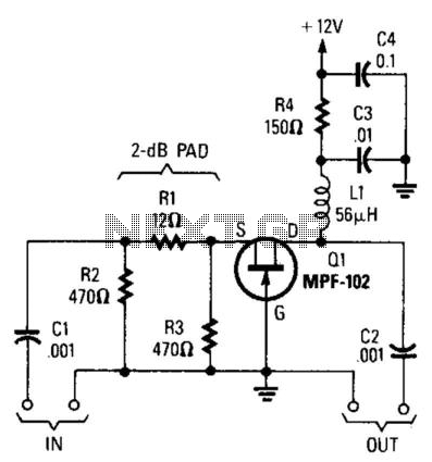
Using an MPF102 JFET, this circuit has a 50-ohm input impedance. The load impedance should be approximately 470 ohms. A 3:1 matching transformer can be utilized to return the impedance to 50 ohms. This circuit will exhibit a gain...
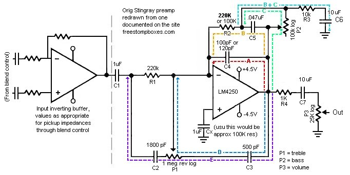
The schematic presented is for the original Music Man Stingray bass guitar preamp. It operates on a 9V DC power supply, and the voltage divider section has been omitted. The Music Man Stingray bass guitar preamp circuit is designed to...

This project involved the design of an audio amplifier that delivers substantial output power while maintaining a minimal parts count and high quality. The power amplifier section utilizes only three transistors along with a few resistors and capacitors arranged...
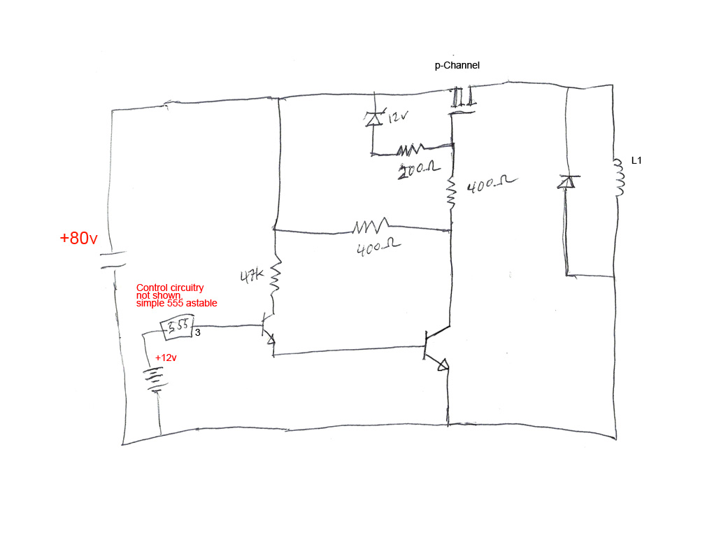
The circuit's premise involves powering an L1 coil with square pulses. A freewheeling diode is included to manage the back EMF field collapse, thereby protecting the circuitry. Previous experiments indicated that using an N-channel MOSFET on the high side...
A popular project among microcontroller enthusiasts is to build a radio-controlled clock. Tiny receiver boards are available, featuring a pre-adjusted ferrite. The radio-controlled clock project leverages a microcontroller to receive time signals transmitted from a time signal transmitter, typically operated...