
Field-strength meter

The described antenna system employs a compact design, utilizing insulated stranded wire approximately 20 cm in length. This wire is strategically arranged within a small plastic enclosure, which serves both to protect the antenna and to facilitate its installation. The choice of insulated stranded wire ensures flexibility and durability, making it suitable for various applications.
The RF current generated by the antenna is processed through a rectification stage involving two diodes. This configuration allows for the conversion of alternating current (AC) signals into direct current (DC), which is essential for further signal processing or measurement. The selection of diodes is critical; they should be chosen based on their forward voltage drop, reverse recovery time, and maximum current rating to ensure efficient rectification.
To provide adjustable output for measurement purposes, a 10 k potentiometer is integrated into the circuit. This component allows for variable attenuation, enabling the user to fine-tune the signal level before it is presented to the meter. The potentiometer's resistance value is suitable for applications where moderate signal levels are encountered, and it allows for a significant range of adjustment to accommodate varying input signal strengths.
Overall, this antenna system is designed for effective RF signal reception and measurement, with a focus on compactness and user adjustability. The combination of the antenna design, rectification stage, and attenuation control creates a versatile tool for various electronic applications.The antenna consists of about 20 cm of insulated stranded wire glued or taped around the inside of a small plastic box. RF current is rectified by two diodes, and a 10 k potentiometer provides variable attenuation for the meter. 🔗 External reference
Related Circuits
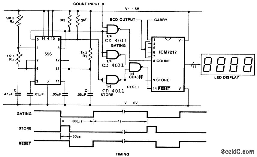
This is an inexpensive frequency counter and tachometer circuit. It utilizes a 556 dual timer to generate the gating, not-store, and not-reset signals for an ICM7217 counter. One timer operates as an astable multivibrator using resistors RA, RB, and...
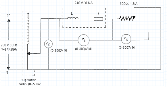
The parameters of the choke coil that will be measured using the three-voltmeter method include inductance and resistance, as all choke coils possess inherent resistance in addition to their inductance. Additionally, the quality factor and power absorbed by the...
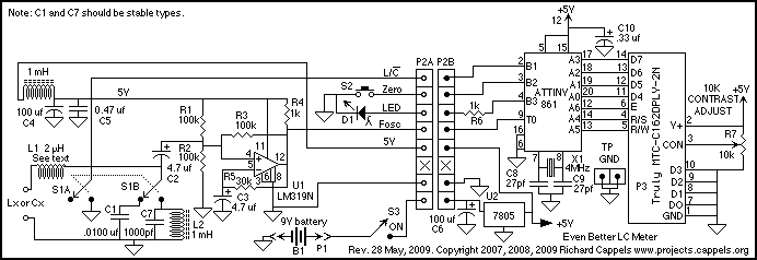
If this picture above looks a lot like the Pretty Good LC Meter also on this web site, that's because it's the same meter, but with some significant improvements. At this point, it's a good idea to read the...
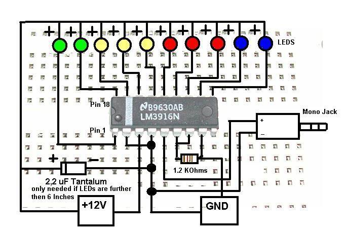
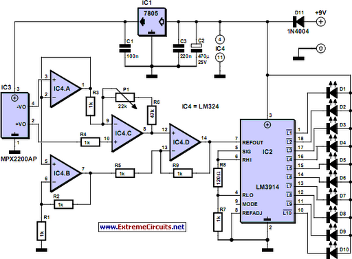
This is a concise guide for constructing a stereo VU meter utilizing the LM3915/LM3916 integrated circuits. The LM3916 is designed to convert analog voltage levels into visual representations through the activation of 10 LEDs, LCDs, or vacuum fluorescent displays,...
While it may lack the aesthetic appeal of traditional mercury barometers featuring elongated glass tubes mounted on intricately carved wood, the Torricelli barometer presented here serves as a functional equivalent and an electronic representation of the original Torricelli barometer....
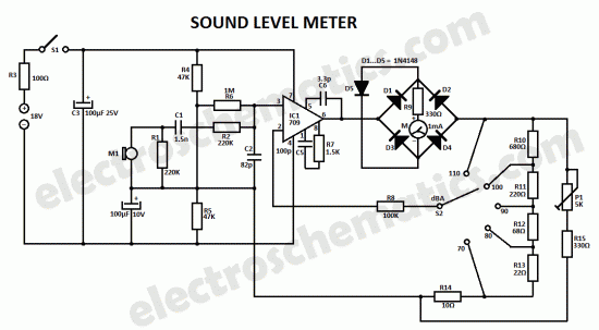
This sound level measuring device circuit can be used to control the intensity of a sound recording in the field of a disco. It has five measurement ranges between 70 and 120 dB, with a measurement accuracy of 0.5...