
firework launcher

The firework ignition system is designed to safely and effectively initiate fireworks using common electronic components. The system typically consists of a power source, a triggering mechanism, and an ignition circuit.
The power source can be a battery or a DC power supply, providing the necessary voltage and current to activate the ignition system. A common choice for such applications is a 9V battery, which offers a suitable voltage level for most ignition circuits.
The triggering mechanism may involve a simple switch or a more sophisticated control system, such as a remote control or a timer circuit, allowing for precise ignition timing. For remote operation, a wireless RF module can be employed, enabling the user to ignite the fireworks from a safe distance.
The ignition circuit usually includes a resistor, a capacitor, and an igniter. The igniter is often a commercially available electric match or a fuse, which ignites when sufficient current passes through it. The resistor limits the current to protect sensitive components, while the capacitor can be used to store energy and provide a quick discharge to ensure reliable ignition.
Safety precautions are paramount when constructing and using a firework ignition system. All components should be rated for the voltage and current they will handle, and the system should be tested in a controlled environment before actual use. Proper insulation and secure connections are essential to prevent accidental ignition and ensure the safety of the operator and the surrounding area.
Overall, the design and implementation of a firework ignition system require careful consideration of the components used, their arrangement, and adherence to safety standards to achieve effective and safe operation.An article describing how I made a firework ignition system out of a few things I picked up at Walmart and Radio Shack.. 🔗 External reference
Related Circuits
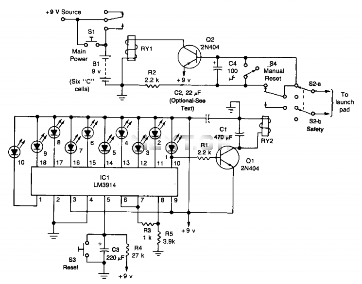
The circuit comprises a launch timer and an automatic-off timer. Upon applying power to the integrated circuit (IC), the countdown LED sequence activates until all LEDs are illuminated. When the last LED (LED1) is fully lit, transistor Q1 enters...
This launch controller can be used with low voltage battery igniters, which fire rocket engines in model rockets such as the Estes range. These circuits are electrical, only switches and contacts are involved. First the circuit for a single...
The electromagnetic ring launcher consists of four subcircuits: a clock circuit built around U5, a 555 oscillator/timer configured for astable operation; a countdown/display circuit built around U3, a 74190 synchronous up/down counter with BCD outputs configured for countdown operation;...
This is a fun and non-dangerous project for those people who like to throw projectiles magnetically. It simply works by placing a ferromagnetic projectile at one end of a coil and pulsing some power in it. The trick is...
A 12V battery pack from a PowerWheels car is used alongside two wooden planks with several nails driven through them. Each nail is wrapped with speaker wire that connects to ignitors, while the other end returns to a central...
This is a fun and non-dangerous project for individuals interested in launching projectiles using magnetic forces. The mechanism operates by positioning a ferromagnetic projectile at one end of a coil and applying a power pulse. The critical aspect is...