
Fluid level control schematic diagrams
The LM1830 fluid level detector circuit provides a highly efficient solution for fluid level monitoring and control. Its design allows for flexibility in probe configuration and integration into various applications, making it a versatile choice in modern fluid management systems. The use of AC signals enhances the longevity and reliability of the probes, while the incorporation of CMOS technology allows for precise control of external devices, such as pumps and valves. This circuit not only improves operational efficiency but also reduces the risk of failure associated with traditional mechanical systems, thus ensuring a more dependable and cost-effective approach to fluid level detection and management.The LM1830 fluid level detector circuit is a device intended to signal the presence or absence of aqueous solutions, featuring low external parts count, wide supply operating range, internally regulated supply and AC or DC output. In a typical application where the device is employed for sensing low water levels in a tank, a simple steel probe may
be inserted in the top of the tank with the tank grounded. When the water level drops below the tip of the probe, the resistance will rise between the probe and the tank and the alarm will be operated. When a non-conductive container is used, the probe may be designed in a number of different ways like a simple phono plug or other probe designs such as conductive parallel strips on printed circuit boards.
Many opportunities exist for a device that can reliably control the operation of pumps or solenoid actuated valves in fluid level control applications. Applications include sump pumps, washing machines, bilge pumps, humidifiers, plating baths, coffee makers, water and waste treatment plants, cooling towers, refrigeration equipment and many others.
In the past these needs have been met by various mechanical arrangements such as float valves or diaphragm actuated switches. These devices were bulky, inaccurate and, because they contain moving parts, often unreliable with disastrous results when they fail.
They are easily disabled by debris or environmental problems such as ice. They can be wery expensive when used to control the level of corrosive fluids such as detergents or plating baths, or when used to control large differences in depth such as in municipal water towers. Mechanical control devices are prone to false actuation in vehicular applications due to their own inertia.
In many applications such as coffee makers, they are too bulky to fit within the package. By utilizing electronic means based on the LM1830 ic, problems inherent in mechanical solutions are overcome and a reliable, cost effective approach to fluid level control is made possible. The LM1830 is an integrated circuit designed to detect the presence or absence of aqueous fluids. An AC signal generated on-chip is passed through two probes within the fluid. A detector determines the presence of the fluid by using the probes in a voltage divider circuit measuring the signal level across the probes.
The AC signal is used to prevent plating or dissolving of the probes as occurs if a DC signal is used. A pin is available for connecting an external resistance in cases where the fluid impedance is not compatible with the internal 13kohms divider resistance.
The addition of a CD4066 quad CMOS analog switch allows the LM1830 to be used for high/low limit control applications. The switch sections are opened and closed by the control signal. Grounding the input of one switch section and pulling its output up with a resistor creates an inverter.
Probes are connected to the inputs of two of the remaining analog switches. Their outputs are connected to the pin 10 of the LM1830 IC (the detector input). The remaining section of the CD4066 IC is used to buffer the open collector output of the LM 1830. All of the control inputs of the analog switch are tied to this output. The last switch section controls the base of a transistor which in turn drives a relay or a solenoid actuated valve. The start and stop probes are set at their appropriate levels in the fluid container, and the ground return is connected to a third probe located at a depth greater than the start and stop probes.
If the container is conductive, it may be used as the ground return. When he fluid reaches a predetermined level, no fluid is covering either of the probes, the pin 12 of the LM1830 switches low. This disables the relay and enables the analog switch connected to the start probe. The fluid eventually fills the container, covering the start probe. When this occurs, the output of the LM1830 swit 🔗 External reference
Related Circuits
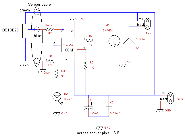
This is a fan controller designed for an audio/video cabinet. It utilizes a PICAXE 08M microcontroller and a DS18B20 temperature sensor. The fan activates at 30 degrees Celsius (approximately 86 degrees Fahrenheit) and deactivates at 28 degrees Celsius (around...
The circuit utilizes two white LEDs, with the second LED connected across the emitter of the transistor and the negative ground. It requires its own limiting resistor in series, similar to R15 and D3 in the circuit diagram. If...
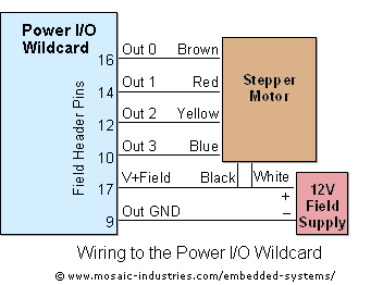
For optimal efficiency, set MAX_STEPPERS to the number of stepper motors being controlled, with a maximum limit of four. Motors are identified by indices 0, 1, 2, and 3. On the QCard, there is a trade-off between the number...
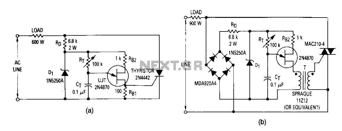
The most elementary application is a half-wave control circuit. The thyristor is acting both as a power control device and as a rectifier, providing variable power to the load during the positive half cycle and no power to the...
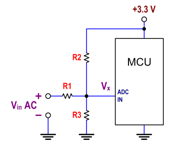
The ATtiny24 microcontroller's ADC is utilized to record an AC signal, which operates within a voltage range of 0 to 3.3V. A precision rectifier is employed to eliminate the negative portion of the signal. The circuit incorporates an LMC6484...
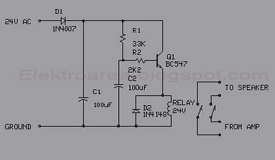
This circuit was designed for an audio amplifier project to control the speaker output relay. The primary function of this circuit is to manage the relay that activates the speaker output in the audio amplifier. The circuit introduces a...
Warning: include(partials/cookie-banner.php): Failed to open stream: Permission denied in /var/www/html/nextgr/view-circuit.php on line 713
Warning: include(): Failed opening 'partials/cookie-banner.php' for inclusion (include_path='.:/usr/share/php') in /var/www/html/nextgr/view-circuit.php on line 713