
FM/PM Demodulation The Phase Lock Loop
The LO port allows the application of a voltage between two points in the circuit, resulting in high resistance. Consequently, the circuit behaves as a direct connection between the two transformers through the conducting diodes. When applying an LO voltage such that one point is negative compared to the other, the circuit can be shown to behave differently, allowing for signal inversion or unaffected passage depending on the applied LO polarity. A real DBM requires a minimum amplitude of LO voltage, typically around 1 V peak-to-peak for silicon or GaAs diodes, to ensure proper operation. DBMs can function at frequencies ranging from below 1 MHz to tens of GHz, with equivalent configurations suitable for millimeter-wave and terahertz frequencies.
In a PLL, the DBM operates in conjunction with a low-pass filter, serving as a phase detector. The output of the system is influenced by the amplitude of the input signal multiplied by the cosine of the phase offset between the signal and the local oscillator (LO) inputs to the DBM. This phase offset is referred to as the phase error, indicating the deviation from quadrature. The PLL continuously adjusts the voltage-controlled oscillator (VCO) output to maintain phase quadrature, ensuring that any changes in the input FM wave's frequency or phase produce a corresponding DBM output that enables the VCO to track the input signal. This relationship necessitates that the frequencies of the two signals remain synchronized. The PLL discussed is a simple first-order loop, although more complex loop types exist, which may offer enhanced performance but are more challenging to analyze. One notable feature of the PLL is its ability to disregard fluctuations in the amplitude of the input FM wave, as indicated by the absence of amplitude in the relevant expressions.
The Double Balanced Mixer (DBM) is a crucial component in various RF applications, particularly in frequency modulation demodulation systems. The DBM's design, featuring four diodes and two transformers, allows for effective signal mixing and phase manipulation. By utilizing a balanced configuration, the DBM minimizes unwanted harmonics and improves signal fidelity, making it suitable for high-frequency applications.
The operation of the DBM can be understood through its three ports: the RF port receives the input signal, the LO port applies the local oscillator signal, and the IF port provides the output signal. The interaction between these ports allows for differential signal processing, where the diodes conduct based on the LO voltage applied, leading to the desired signal inversion or direct transmission.
In conjunction with the low-pass filter in the PLL configuration, the DBM acts as a phase detector that continuously monitors the phase relationship between the incoming signal and the VCO output. This feedback loop ensures that the VCO adjusts its frequency to match the incoming signal, thus maintaining a stable demodulated output. The PLL's ability to filter out amplitude variations makes it particularly advantageous in environments with noisy signals, ensuring robust performance in demodulating FM and PM signals.
Overall, the combination of the DBM and PLL offers a versatile and efficient solution for demodulating frequency-modulated signals, enabling precise recovery of the original information contained within the carrier wave.We saw how it is possible to create signals which carry information by modulating the frequency or phase of a carrier wave. Here we`ll examine how it is possible to Demodulate these signals and recover the information. Note that although we`ll concentrate on FM demodulation, similar methods are useful for general measurements of signal frequencies and for PM demodulation.
The most popular electronic` method for FM/PM demodulation is the Phase Locked Loop (PLL). To see how this works we must first explain one of its elements ” the Double Balanced Mixer (DBM). Figure 13. 1a shows the circuit diagram for a DBM. It consists of four diodes linking two transformers. There are three ways or ports by which signals can get in/out of the DBM. It is conventional to call these the RF, LO, and IF ports since DBM`s are often used as mixers in heterodyne systems. To see how the system works we can start by considering the LO port. This lets us apply a voltage between the points A and B in the circuit. will present a very high resistance. As a result, the circuit will behave like 13. 1b. The two transformers will be directly` connected together via the conducting diodes. Using 1:1 transformers and low-loss diodes we therefore find that, when When we apply an LO voltage such that A is negative compared to B we can use a similar argument to show that, in this case, the circuit behaves like 13.
1c. Hence when. We can therefore use the DBM as a sort of switch` to control whether we pass on the the signal unaffected or invert it by applying the required polarity of In practice, a real DBM requires a given minimum amplitude of LO voltage to ensure the diodes have turned on/off` properly. For typical silicon or GaAs diodes this usually means we need about 1 Vptp of LO at the diodes. DBM`s of this type can be used for frequencies from below 1 MHz to tens of GHz. Equivalent arrangements (using other items in place of ordinary transformers) can be used at mm-wave & THz frequencies.
In a PLL, the DBM is used in combination with a low pass filter (or time constant) as a Phase Detector. To understand how this works, consider the situation illustrated in figure 13. 2. over one cycle and dividing by the cycle period. (Since every cycle is just like the others this gives the same result as averaging over many cycles. ) i. e. we can say that The amount by which the output ripples` up and down above this average value will depend upon the details of the low pass filter.
Here we can ignore this ripple and just assume that we get an output proportional to the input level`s amplitude multiplied by the cosine of the phase offset, j, between the signal and lo inputs to the DBM. The system therefore provides an output which depends upon this phase. is called the phase error between the input signal and VCO output. (Note that this is actually the angle by which they depart from being in quadrature. ) For similar reasons it is conventional to call A more general explanation of the PLL`s behaviour is that it continuously adjusts the VCO output to maintain phase quadrature.
Any change in the input FM wave`s frequency or phase tends to produce a DBM output which causes the VCO to track` the input. For the two to maintain a constant phase relationship they must keep in step` ” i. e. their frequencies must always be the same. Since the VCO`s frequency depends upon the control voltage, provide us with the demodulated pattern we require.
The PLL we`ve considered is called a simple First Order loop. More complex types of loop also exist. These often work better but are harder to analyse. Their basic operation is the same as the system we`ve considered. The PLL has some interesting features. The most useful of these is that it largely ignores fluctuations in the amplitude of the input FM wave. (You can see this is true because expression 13. 28 doesn`t include the input wave`s amplitude, . ) This me 🔗 External reference
Related Circuits
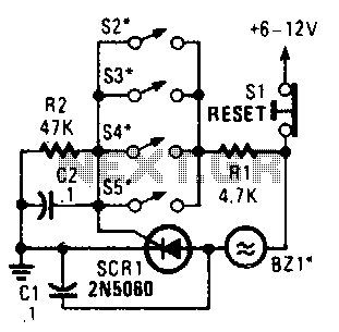
Four parallel switches are employed to monitor four positions. When any switch is closed, SCR1 is triggered, activating the alarm. The alarm is designed to be of the non-interrupting type. The circuit consists of four parallel switches, each representing a...
This circuit is a two-wire light level detector. The power supply and output signal are delivered through the same wires, utilizing a current loop. This two-wire light level detector circuit operates by using a single pair of wires for both...
The TBA120U is an intermediate frequency (IF) amplifier that includes a symmetrical frequency modulation (FM) demodulator and an audio frequency (AF) amplifier with adjustable output voltage. The AF amplifier features an output for volume control and an input for...
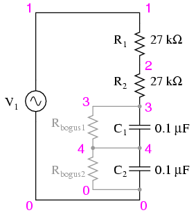
Construct the circuit and measure the voltage drops across each component using an AC voltmeter. Additionally, measure the total (supply) voltage with the same voltmeter. It will be observed that the individual voltage drops do not sum up to...
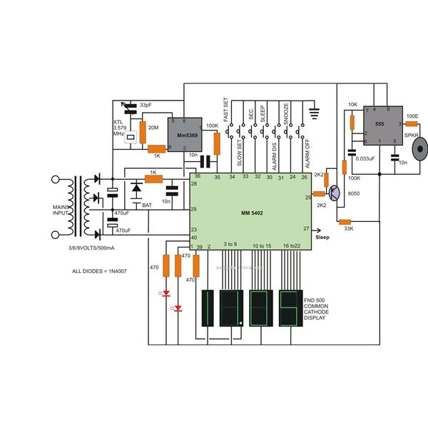
Creating a high-end, precise digital LED clock is now as straightforward as preparing noodles. This article outlines the process of constructing a digital clock using readily available electronic chips, such as the National Semiconductor MM5402 clock IC, along with...
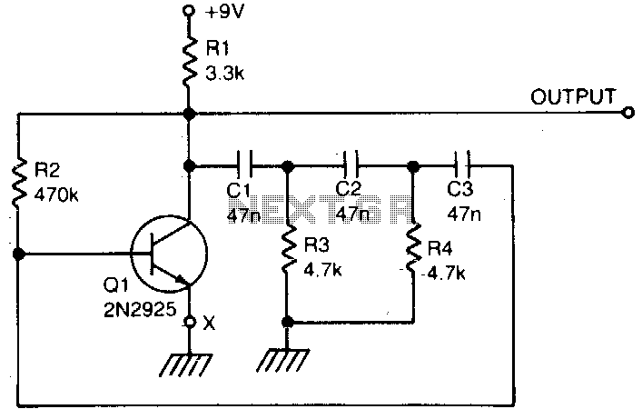
A single transistor is utilized to create a simple phase shift oscillator. The output produced is a sine wave with a distortion level of approximately 104. The purity of the sine wave can be improved by incorporating a variable...