
FM surveillance BuG Transmitter

The described circuit functions as a low-power FM transmitter, suitable for voice transmission within the FM radio band. The operating frequency range of 88 to 108 MHz is standard for commercial FM radio stations, allowing the circuit to be compatible with most FM receivers. The circuit design typically includes a microphone for audio input, an oscillator circuit to modulate the audio signal onto the carrier frequency, and an output stage to amplify the modulated signal for transmission.
To optimize performance, the trimmer capacitor is used to fine-tune the oscillator circuit, ensuring that the transmitted signal is within the desired frequency range. This adjustment is crucial for minimizing interference with other radio signals and maximizing clarity in audio transmission.
The power requirements indicate a low-power design, with a maximum current consumption of 30 mA, making it energy-efficient. The option to use a 9-volt battery or an external power supply ranging from 9 to 12 volts provides flexibility in powering the circuit, catering to various applications and user preferences.
Additional components may include resistors and capacitors for filtering and stability, and an antenna to enhance the transmission range. The overall design should ensure that the circuit is compact and portable, suitable for various environments where voice transmission is needed. Proper assembly and tuning are essential to achieve optimal performance and avoid regulatory issues related to unauthorized transmission in the FM band.The Circuit shown can transmit voice to exceptionally good range. Tune trimmer to hear the signal to your near radio. Frequency range is 88-108 MHz. Max current consumption is 30mA. You can power the bug with a 9Volt Battery, or you can plug a power supply to feed in 9-12 Volts. Source: NEXT.GR.. 🔗 External reference
Related Circuits
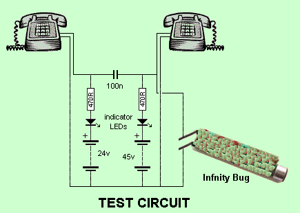
At this stage, a whistle is directed into the receiver, and the Infinity Bug will activate. The high-gain amplifier within the Infinity Bug captures audio from its location. It can only be assembled on the provided PC board since...

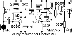
The moderate power FM transmitter circuit employs two transistors. The voice signals picked up by the microphone will be amplified by the transistor. The described FM transmitter circuit utilizes two transistors to facilitate the modulation and amplification of audio signals....

A 4 to 20 mA current transmitter circuit is implemented using the MAX1459, as illustrated in the accompanying figure. The output voltage from the programmable gain amplifier (PGA) is supplied to a spare amplifier chip, and subsequently, an external...
The FM Wireless Microphone has gained popularity among both beginners and experienced constructors. It has been utilized in guitars and as a component of remote control systems. There have been numerous requests for a higher-powered circuit with improved microphone...

This compact transmitter employs a Hartley oscillator configuration. Typically, the capacitor in the tank circuit connects to the base of the transistor; however, at VHF frequencies, the base-emitter capacitance of the transistor behaves like a short circuit, maintaining its...

The pressure transmitter circuit data acquisition system utilizes the 1B31, an 18-bit A/D converter (AD1170), and an MCS-51 microcontroller. The configuration, as depicted in the accompanying diagram, features a full-scale output voltage of 10 mV from the pressure transmitter...