
fogger timer
The custom fogger timer circuit is designed to enhance the efficiency of fog production during Halloween festivities, ensuring that the fogger operates only when needed. The use of an IEC extension cable allows for a seamless connection to the existing fogger control system, while the incorporation of a relay ensures safe operation with high voltage. The microcontroller, PIC16F84, provides precise control over the fogger's operation, enabling programmed intervals for fog emission. The use of an optoisolator enhances safety by isolating the microcontroller from the high voltage circuit, while the 2N2222 transistor acts as a switch to control the relay. The design prioritizes safety and reliability, with protective measures such as liquid electrical tape and a secure enclosure for the relay. The standby indicator feature adds an additional layer of control, allowing the user to manage when the fogger is active, thus optimizing fog production for maximum effect during the event. Overall, this circuit serves as an effective solution for managing fogger operation in a dynamic environment, ensuring an engaging Halloween experience.On Halloween night, I reguarly have periods of 5, 10, and even 15 minutes where no ToTs are around. It seemed kind of silly to me to have the fogger spewing fog during such breaks by using a standard fogger timer. Instead, I decided to build my own custom fogger timer. I picked up an IEC extension cable, which has the kind of connector my foggercontrol button has. I cut the other end of the cable off so that I could get at the wires. Next, I opened up button controller that came with the fogger. Using my multimeter in "continuity check" mode, I determined which 2 pins of the connector were connected to either side of the button in the controller. I have no idea how standard this configuration is, but in my case, it was the middle pin and the right pin, as indicated in the picture: Now, using the multimeter again, determine which 2 wires on the extension cable match up with those same 2 pins from the original connector.
These are the wires that need to be connected to one side of a relay. It doesn`t matter which wire goes to which pin of the relay. Since 110V runs through this cable, I didn`t want the relay pins exposed so that they could come into contact with anything, so before soldering the wires onto the relay, I purchased a plastic electrical box and ran the wires into that. I then soldered the 2 wires onto the relay. I also soldered 2 short control wires onto the pins connected to the coil of the relay. I soldered the other ends of the control wires onto the pins of a terminal block that I mounted on the side of the electrical box, drilling a couple of small holes for the pins of the terminal block to pass through.
I also soldered a diode across the 2 pins of the coil of the relay. Once all this was soldered up, and I had verified that the connections were good, I glued the relay, pins up, to the bottom of the electrical box. Then, I coated all the exposed metal with "Liquid Electrical Tape" to help protect everything just in case something ever pulled lose.
Basically, the way it works is this: When voltage is applied to the pin labeled as "To microcontroller output pin", the LED inside the optoisolator (the NEC 2501) turns on. This causes the transistor in the other half of the opto to start conducting. This causes current to flow through the base of Q1, a 2N2222 transistor, which causes it to start conducting.
This closes a path to ground for both the LED and the relay coil, which turns them both on. I am using a PIC16F84 to control the circuit above. I would have liked to have used some potentiometers to control on and off times, but I was having difficulty getting those working, so I simply hard-coded the on and off times into the PIC. The only other input I have going to the PIC is my "standby indicator". There is a push button just inside the garage door. When pushed on, a voltage is applied to wires going throughout the garage. Most of my props look for this signal. If this signal is absent, the prop doesn`t fire. In other words, the props will only fire if the standby indicator is on. The fogger timer will work similarly. As long as the standby indicator is off, the fogger will never run. When the standby button is pressed, the fogger will fire for some number of seconds (currently 30, but I may need to adjust it after performing some tests).
After that, it will turn off and on at predetermined intervals until the standby button is switched off. 🔗 External reference
Related Circuits
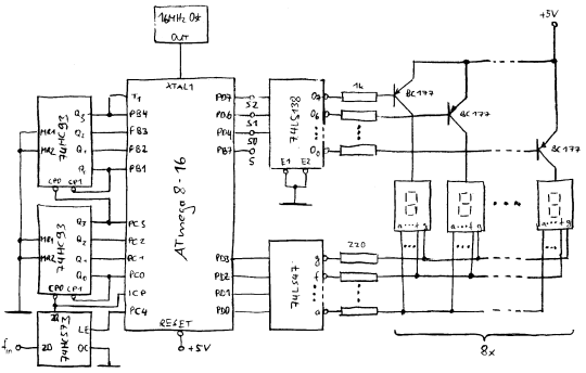
In counter mode, it provides 1 Hz resolution up to 100 MHz. In timer mode, the maximum resolution is 0.0000001 Hz up to 1 Hz. The resolution decreases by one digit for each additional decade. Multiple frequency updates per...
The 555 IC is a widely used component for timer circuits. By incorporating an integrator circuit, it is possible to extend the timing period of the 555 IC timer while maintaining a reasonable capacitor size. The 555 timer IC is...

This is a simple smoke alarm circuit using a timer IC, the NE555. The circuit operates by illuminating a Light Dependent Resistor (LDR) with a lamp. When smoke obscures the light from the lamp, the resistance of the LDR...
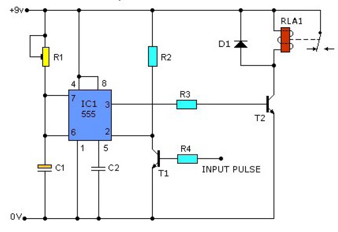
This causes T1 to conduct, pulling pin 2 of IC1 low. IC1 then enters a timing cycle, the duration of which is set by R1 and C1, resulting in pin 3 of IC1 going high. This action causes T2...
This circuit provides a visual 9-second delay using 10 LEDs before closing a 12-volt relay. When the reset switch is closed, the 4017 decade counter resets to the 0 count, illuminating the LED driven from pin 3. The 555...
Turns off your amplifier when idle for 15 minutes. Fed by amplifier tape-output. This circuit turns off an amplifier or any other device when a low-level audio signal fed to its input is absent for 15 minutes at least....
Warning: include(partials/cookie-banner.php): Failed to open stream: Permission denied in /var/www/html/nextgr/view-circuit.php on line 713
Warning: include(): Failed opening 'partials/cookie-banner.php' for inclusion (include_path='.:/usr/share/php') in /var/www/html/nextgr/view-circuit.php on line 713