
Four-decade variable oscillator
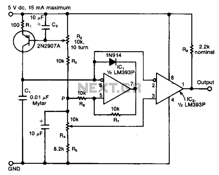
The described circuit operates as a variable-frequency pulse generator, utilizing a combination of capacitive charging and comparator switching to produce a precise output waveform. The first stage involves the charging of capacitor C1 by a nonlinear current source, which is controlled by the 2N2907A PNP transistor. The transistor's base current is influenced by resistor R1 and the adjustable potentiometer R2, allowing for fine-tuning of the charging rate and, consequently, the frequency of the generated sawtooth waveform.
The Schmitt-trigger comparator plays a crucial role in ensuring that the capacitor discharges rapidly, creating sharp transitions in the voltage across C1. This rapid discharge leads to the generation of a sawtooth waveform, which is characterized by a linear rise followed by a quick drop, suitable for pulse-width modulation applications.
The second comparator receives the sawtooth waveform and compares it against a variable reference voltage, which is set by the user. This variable switching level allows the output pulse train's duty cycle to be adjusted independently of its frequency. The output of the second comparator is a series of pulses, whose frequency and duty cycle can be modified based on the settings of the potentiometer R2 and the reference voltage.
In addition, capacitor C2 serves an important filtering function, smoothing out any high-frequency noise or ripple that may be present at the base of the transistor. This filtering is essential for maintaining the stability of the frequency output, as any noise could introduce jitter, affecting the performance of the pulse generator.
Overall, this circuit design provides flexibility and precision in generating variable-frequency pulse trains, making it suitable for various applications in signal processing, control systems, and waveform generation.The circuit consists of a variable current source that charges a capacitor, which is rapidly discharged by a Schmitt-trigger comparator. The sawtooth waveform thus produced is fed to another comparator, one with a variable switching level.
The output from the second comparator is a pulse train with an independently adjustable frequency and duty cycle. The variable-frequency ramp generator consists of capacitor Cl, which is charged by a variable and nonlinear current source.
The latter comprises a 2N2907A pnp transistor, plus resistor Rl and the potentiometer R2. Capacitor C2 eliminates any ripple or noise at the base of the transistor that might cause frequency jitter at the output. 🔗 External reference
Related Circuits
Online Electronics Course covering the Science of Radio Frequency Engineering, including topics such as Electronics, Microwave Technology, Waveguides, Antennas, Tubes, Historical Context, Klystrons, Magnetrons, Traveling Wave Tubes (TWT), Internet of Things (IoT), Klystrodes, Broadcast Equipment, and Repair Techniques. The online...
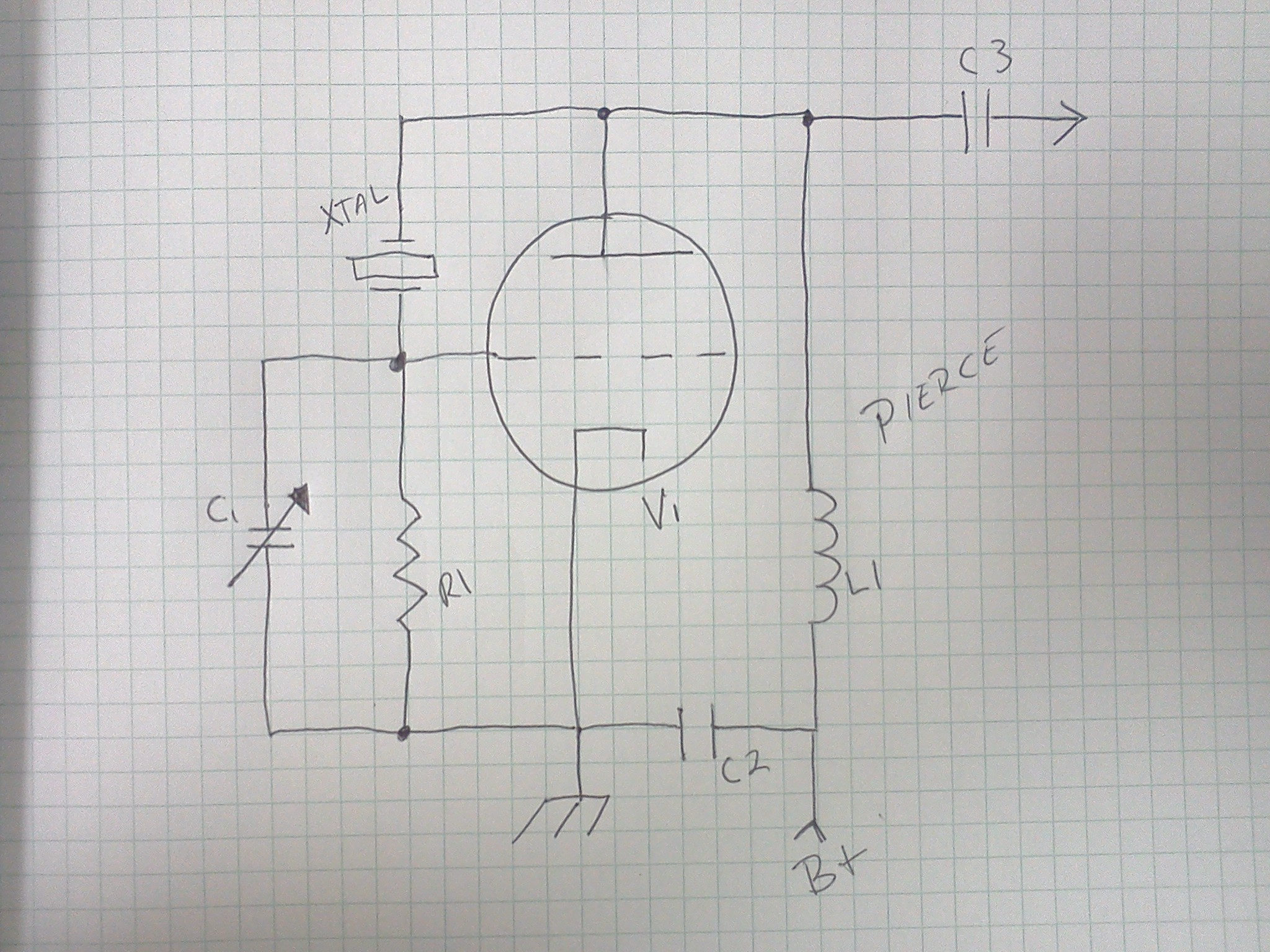
The variations, which effectively form an alternating signal, will be transmitted through the coupling capacitor to the subsequent stage, indicated by the arrow to the right. One variable resistor can be substituted with another. R1 can be replaced with...
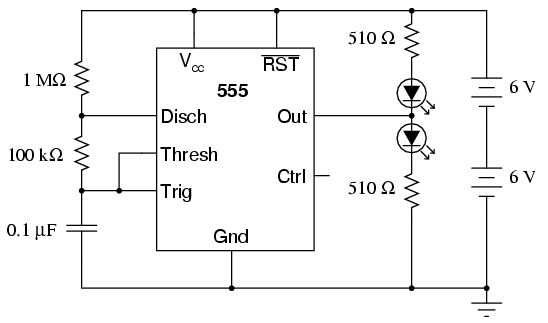
An oscilloscope is useful for analyzing the waveforms produced by this circuit, although it is not essential. An audio detector serves as a valuable piece of test equipment for this experiment, particularly if an oscilloscope is unavailable. The "555"...
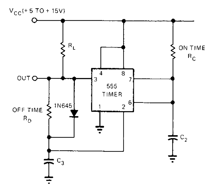
The 555 timer circuit has unsteady open and closing times that are independent of one another. One time constant is given by 1.1RcC2, while another time constant is defined as 1.1RcC3. The free-running period is the sum of these...
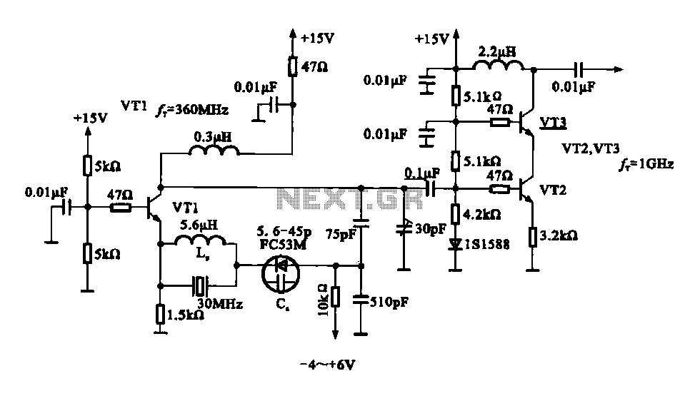
A variable frequency oscillator transistor circuit, primarily functioning as an oscillator, incorporates a crystal resonator and a varactor diode. The output is amplified, typically used for generating high-frequency signals. This 30 MHz transistor circuit features an inductor (LP) connected...
This circuit is a low-frequency Wien bridge sinusoidal oscillator designed for the audio range, characterized by very low distortion, making it suitable for testing various audio equipment. The circuit has undergone thorough testing, and a printed circuit board (PCB)...