
Frequency counter Counter schematic

The circuit design employs five CD40110 integrated circuits, which are known for their versatility in digital counting applications. Each CD40110 chip contains a decade counter that can count from 0 to 9 and includes the necessary logic to control the display and manage the counting process. The cascading of these chips allows for the counting of larger numbers, as the output of one chip can serve as the clock input for the next, creating a multi-digit counter system.
The counting mechanism operates on the principle of detecting the rising edge of the input signal, which triggers the counting process. This feature is critical for applications requiring precise timing and frequency measurement. The integration of a display latch allows for the temporary storage of the counted value, enabling the display to show the last counted number until the measurement is completed.
The CD4044 serves an essential role in managing the overflow and underflow conditions of the counting process. By providing feedback to the logic board, it ensures that the counting system can adapt dynamically to changes in input frequency, thus maintaining accuracy in measurements. This adaptability is crucial in applications where input signals may vary significantly.
The logic board's operation is further refined by the use of control pulses. A LOW pulse directed to the CNT-CTRL latch input transfers the current count value to the display, allowing the user to view the result immediately after measurement completion. Following this, a HIGH pulse resets the counter, preparing it for the next counting cycle. The toggle line, while available for enabling up/down counting, remains unused in this specific application, which simplifies the design and focuses on the up counting functionality.
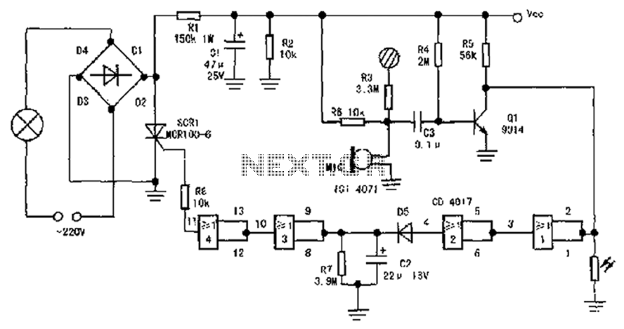
The design also incorporates a voltage sink circuit for the LED displays. This circuit is intended to provide a stable voltage to the LEDs, ensuring consistent brightness and performance. However, the current implementation has been noted to produce undesired fluctuations, indicating that further refinement or redesign may be necessary to achieve the desired stability in LED operation. A more reliable voltage regulation approach would enhance the overall functionality of the display system, ensuring that it meets the performance expectations in various operating conditions.The counter makes use of 5 cascaded CD40110 which combine a decade counter, a display latch and a 7 segment LED driver in a single chip. (The decimal points are driven by IC8x. ) The counter allows up and down counting (although only up counting is used in the frequency counter) and counts on the rising edge.
An over- and underflow indicator is pro vided via CD4044 which is fed back to the logic board to allow automatic adaption of the divider or gate time if the counter has an overflow. In normal (e. g. frequency or time measurement) operation, CD40110 is used to count the input signals "in background" while still displaying the old content.
Then, when the measurement is done, the logic board provides a LOW pulse on the latch input of CNT-CTRL to put the counter content into the display latches and hence display it on the LEDs, then reset the counter (and overflow indicator) using a HIGH pulse to the reset line. The toggle line can be used to enable the up/down clock but is not used in the frequency counter. The circuit on the left bottom is thought to provide a constant voltage sink for the LEDs. Better invent something similar since this circuit does not really work as expected and may tend to swing.
🔗 External reference
Related Circuits
The circuit diagram illustrates a sound, light, and touch-controlled delay self-extinguishing switch. It comprises three main sections: the power circuit, the signal conversion detecting circuit, a delay circuit, and a control circuit. 1. Power Circuit: This section consists of...
Currently, a basic MOSFET amplifier or power amplifier is designed to deliver an output power of ±100 Watts RMS with an 8 Ohm load, or ±160 Watts RMS with a 4 Ohm load. The simplicity of this circuit results...
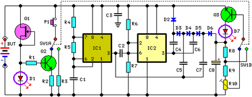
FET Q1 functions as a constant current generator, providing biasing for LED D1 and the base of Q2. This configuration ensures that D1 emits light at a consistent intensity, regardless of the battery voltage, which ranges from 3 to...

This design circuit is a tachometer circuit based on the LM2907 integrated circuit, which can provide zero-crossing data to a digital system. At each zero crossing of the input signal, the charge pump alters the state of capacitor C1...
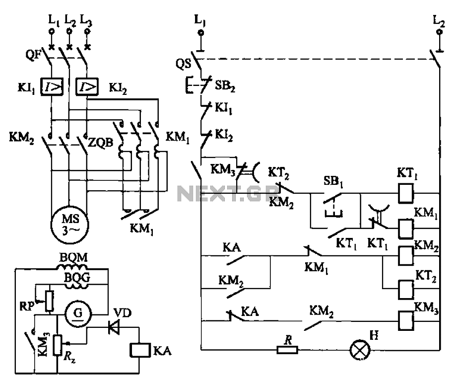
The circuit depicted in Figure 3-187 illustrates the operation of an auto step-down transformer (ZQB). Upon activation, the ZQB transformer initiates a sequence that allows the motor to gradually increase its speed. After a predetermined delay, the ZQB ceases...
Switching regulator subsystems are designed for use as DC to DC converters. The 3V to 40V DC converter circuit utilizes switching regulators, which are increasingly favored over linear regulators due to the demand for higher conversion efficiency in modern...