
frequency doubler with 4069
The frequency doubler circuit utilizing the 4069 hex inverter IC is an efficient method for generating a signal at double the frequency of the input. The 4069 is a quad inverter, which means it contains four independent inverter gates, allowing for versatile designs.
To construct the frequency doubler, the circuit typically consists of one inverter from the 4069 IC, connected to the input square wave signal. The output of this inverter is then fed into a second inverter, creating a feedback loop that generates oscillations. The feedback is achieved through a resistor-capacitor (RC) network, which determines the timing characteristics of the circuit.
The input square wave signal is applied to the first inverter, which inverts the signal. The output from the first inverter is then connected to an RC network, consisting of a resistor (R) and capacitor (C). This RC network introduces a phase shift that is crucial for frequency doubling. The output of the RC network is then fed into the second inverter, which further inverts the signal.
The result is a pulse train at the output that has a frequency that is twice that of the original input signal. The output can be observed using an oscilloscope, which will display a waveform with a frequency that is double that of the input square wave.
This frequency doubler circuit is useful in various applications, including signal processing, modulation, and clock generation in digital circuits. The simplicity of using a single IC makes it an attractive solution for designers looking to implement frequency doubling in their projects. Proper selection of the resistor and capacitor values is critical, as it affects the performance and stability of the frequency doubling process.This frequency doubler using a single 4069 hex inverter IC, a frequency doubler can be constructed to give an output pulse train whose frequency is twice that of a squarewave input signal.. 🔗 External reference
Related Circuits
The Model LM-13 Crystal Calibrated Frequency Indicating Equipment has been specifically designed to provide a simple, accurate, and reliable frequency indication for the crystal calibrated type, intended for use in the U.S. Naval radio service. It is adaptable for...
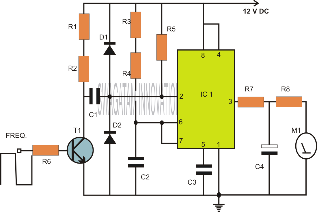
Power the frequency counter and adjust the coarse (top pot) and fine (bottom pot) controls to display zero frequency. Turn the pots counter-clockwise to achieve a zero reading. Occasionally, the counter may show only squares without digits. If this...
This is a classic divider of frequency via two. It is achieved with a classic circuit T-flipFlop, round IC1 [4011]. In the circuit, the frequency of network, after are limit the negative half-s period of sine wave and transform...
Capacitors are major electronic components classified as passive components. They are extensively used in electronic circuits, and virtually no circuit can be constructed without these essential parts. The primary function of a capacitor is to block direct current (DC)...

This is a CMOS-compatible (and ideally also TTL-compatible) input that includes over-voltage and under-voltage protection. Schmitt triggers are utilized to accommodate inputs with long transition times. It has been verified to function at frequencies up to 30 MHz. The described...
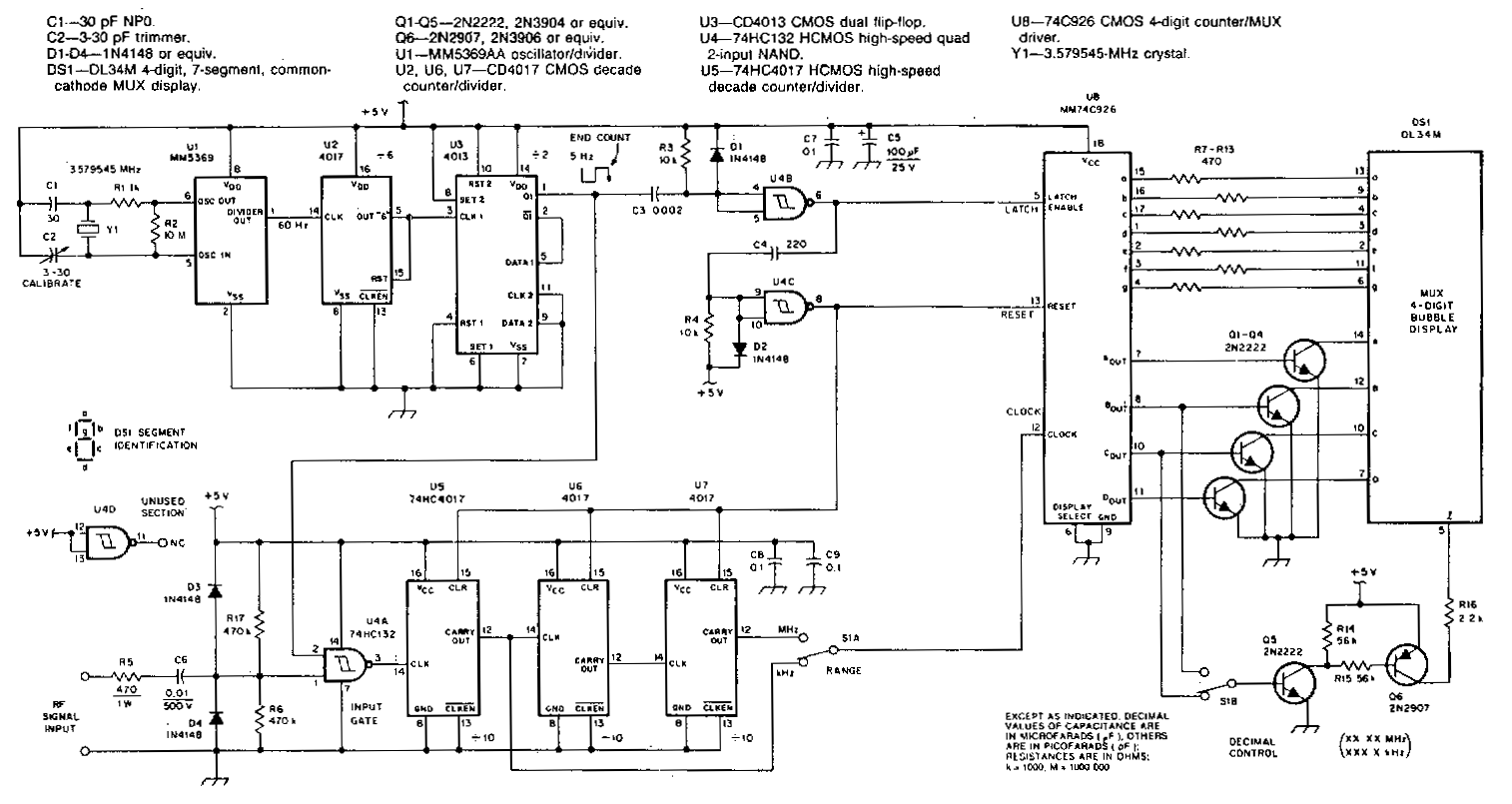
This counter features a four-digit display that can be switched to display frequencies ranging from 1 to 40 MHz, with a resolution of 100 Hz. The MM74C926 CMOS IC serves as the four-digit decimal counter, which can latch a...
Warning: include(partials/cookie-banner.php): Failed to open stream: Permission denied in /var/www/html/nextgr/view-circuit.php on line 713
Warning: include(): Failed opening 'partials/cookie-banner.php' for inclusion (include_path='.:/usr/share/php') in /var/www/html/nextgr/view-circuit.php on line 713