
HETERODYNE FREQUENCY METER
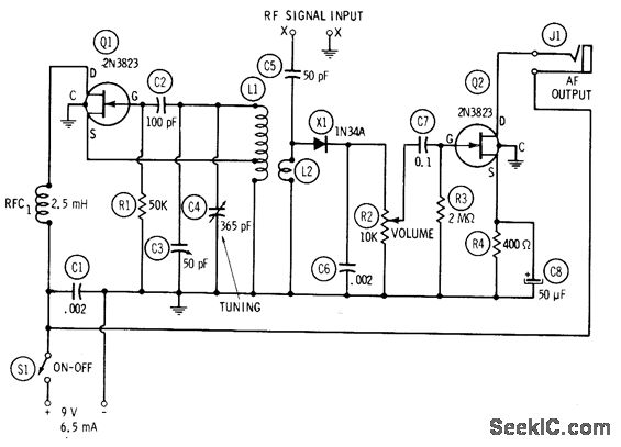
The circuit is designed to operate within a frequency range of 1 to 40 MHz, utilizing a combination of oscillation and mixing techniques to detect and analyze RF signals. The oscillator (Q1) generates a stable frequency output, which serves as a reference for the untuned mixer (X1). The mixer facilitates the combination of the unknown RF signal with the oscillator's output, producing an intermediate frequency that can be processed by the audio frequency beat-note amplifier (Q2).
The calibration of capacitor C4 is critical for accurate frequency measurement. It allows for direct readings of the oscillator frequency, ensuring that the system can effectively zero-beat with the incoming RF signal. The zero-beating technique is essential for identifying the frequency of the unknown signal, as it relies on achieving a condition where the beat frequency is minimized, resulting in an audible tone through the connected magnetic headphones.
The use of inductors L1 and L2 is significant in the circuit's design. L1, with its 65 turns, provides the necessary inductive reactance to facilitate the mixing process, while L2, with its 10 closely wound turns, enhances the circuit's performance by improving the coupling between the oscillator and the mixer. The tapping of L1 at 20 turns allows for flexibility in tuning and adjusting the circuit to achieve optimal performance across the specified frequency ranges.
Overall, this circuit exemplifies a practical application of RF technology in signal detection and analysis, making it a valuable tool for engineers and technicians working in the field of electronics. Its straightforward design and calibration process make it accessible for various applications, including communication systems and signal processing tasks.Circuit consists of 1-2 MHz oscillator Q1, untuned mixer X1, and AF beat-note amplifier Q2. C4 is calibrated to read directly in frequency from 1 to 2 MHz, using accurate unmodulated RF signalgenerator. After calibration, unknown RF signal input frequency is fed into meter for zero-beating with harmonics of calibrated oscillator.
Magnetic headphone s plugged into J1 make beat note audible. On second harmonic, dial of C4 covers 2-4 MHz; on twentieth harmonic, coverage is 20-. 40 MHz. L1 is 65 tums No. 28 enamel on 1-inch form, tapped 20 tums from ground. L2 is 10 tums No. 28 enamel closewound around center of L1. -R. P. Turner, "FET Circuits, " Howard W. Sams, Indianapolis, IN, 1977, 2nd Ed. , p 144-146. 🔗 External reference
Related Circuits
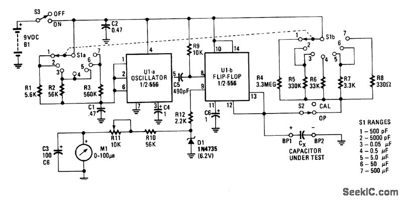
U1a functions as an oscillator, while U1b serves as the measurement component of the circuit. It transforms an unknown capacitance into a pulse-width modulated signal, similar to the operation of an automotive dwell meter. The meter operates linearly, meaning...
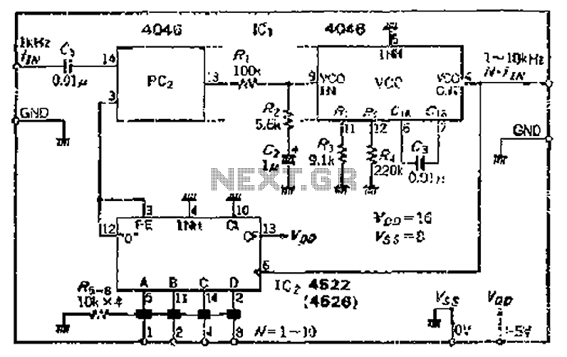
The CMOS IC 4046 Phase-Locked Loop (PLL) operates with a maximum frequency of 1 MHz. It is connected to a programmable divider, allowing it to process input frequencies. As the frequency increases by a factor of t, the circuit's...

I made this project as a test to improve a technique to read analog values without analog-to-digital converter (ADC). I ended with this "sound meter". It may not work perfectly, it needs some improvement but works anyway. It has...
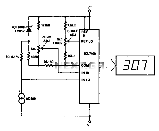
This circuit allows for zero adjustment as well as slope adjustment. The ICL8069 brings the input within the common-mode range, while the 5 kΩ potentiometers trim any offset at 218 K (-55 °C) and set the scale factor. The described...
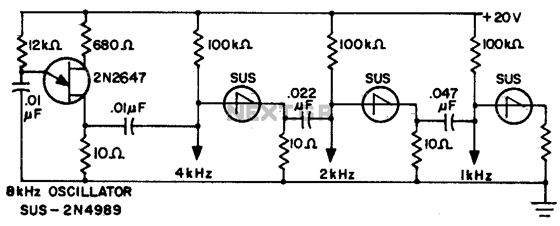
The sawtooth output from each stage is one half the frequency of the preceding stage. The described circuit features a multi-stage sawtooth waveform generator, where each stage produces an output with a frequency that is half of the frequency generated...
The circuit charges and discharges a capacitor at a crystal-controlled rate and stores the change in voltage achieved on a sample-and-difference amplifier. The current flowing during the discharge cycle is averaged and ratiometrically measured in the analog-to-digital converter (ADC)...
Warning: include(partials/cookie-banner.php): Failed to open stream: Permission denied in /var/www/html/nextgr/view-circuit.php on line 713
Warning: include(): Failed opening 'partials/cookie-banner.php' for inclusion (include_path='.:/usr/share/php') in /var/www/html/nextgr/view-circuit.php on line 713