
gate sequencer
The CGS89 sequencer represents a versatile tool for creating complex rhythmic patterns and triggering a variety of modules within a modular synthesizer setup. Its ability to cascade multiple units enhances its functionality, allowing for intricate sequencing and control. The design incorporates a user-friendly interface with switches for customizing output lengths, ensuring adaptability for various musical applications. By utilizing buffered outputs, the sequencer can effectively drive multiple devices simultaneously, providing visual feedback through LED indicators. The integration of an LM339 comparator ensures reliable signal processing, accommodating a wide range of input voltages typical in modular environments. Overall, the CGS89 is a powerful component for musicians and sound designers seeking to expand their creative possibilities in electronic music production.The CGS89 is a sequencer designed for delivering pulsed or gated events, for rhythm and percussion, triggering other sequencers, or selecting stages in Programmers such as the Serge R15 PRG. It can be used as a replacement for the first generation Serge R10 SEQ Sequencer. The main function of the board is as a sequential pulse generator. When cloc ked by an external source, each of its outputs will come on one after the other. This can be used to sequentially trigger up to ten events. An example would be to set the number of steps to 2, then connect outputs 1 and 2 to two drum sound generators. A pulse train fed to the clock input would then produce a drum roll alternating between the two drum sounds.
When coupled with a switch bank and the onboard buffers, rhythms of up to ten steps can be created. There are two onboard buffers, giving two separate channels. While these outputs can be used to trigger drum sounds, that is not their only use. They can be used to trigger envelope generators, step waves in wave tables, drive other sequencers etc. Once you have a gate sequencer in your modular, you will wonder how you ever survived without it. Multiple gate sequencers can also cascaded for longer rhythm lengths, or more channels. To cascade the outputs of several units, simply connect the "Full Out/Mix Out" and "Pulse Out" outputs on the first unit to the corresponding outputs on the second unit and so on.
That is right, this module has been designed so it`s outputs can be connected together with its other outputs, or outputs of other CGS89 gate sequencers via wire ORing. An LM339 comparator is used to shape the input signals. These take whatever signal is fed into the module and convert them to signals appropriate for driving the rest of the circuitry.
With the values given, the sensitivity is set at around 2V, allowing triggering from signals with a +/- 5 volt swing, or with a 0V to +10 volt swing, both of which are common in modular synths. The output waveforms of some modules will never fall below the 1. 4V level, preventing triggering. A gate signal at the Hold input will stop the sequencer, and disable the switched outputs on the other part of the circuit diagram until such a time as the gate signal stops.
A gate signal at the RSP reset input will set the sequencer back to step one, but allow it to keep counting, irrespective of the length of time the gate signal is present. Each of the outputs of the 4017 are buffered with a transistor wired as an emitter follower. Any general purpose NPN transistor will work here. I use the BC547 because it is the most common transistor in Australia. This buffer drives an LED to display which step is active, as well as the individual outputs for each step.
SPDT Center-off switches are used to allow each step to be either the full length of the clock cycle, or gated with the incoming clock pulse. Varying the mark-space ratio of the clock signal can thus be used to vary the length of the output pulses.
The channel outputs F1, F2 (full step length for channel 1, 2) and P1, P2 (partial step length for channel 1, 2) are then fed back to the onboard buffers for processing. Note that diodes are needed for each switch and need to be mounted off-board. All switched signals, both full length and pulses, are mixed and sent to the corresponding Full/Mix output.
Pulses are present at the Pulse output for all stages for which a switch is not off, i. e. , if the switch is set to full, or pulse for a particular stage, there will be a corresponding pulse at the Pulse output. Event Generator concept, example patch. The first CGS89 board is clocked at the frequency of the "master" clock as provided by the onboard LFO (modified CGS58).
The second CGS89 board is clocked by the first stage of the previous CGS89. It advances at 1/10th of the rate. The third CGS89 board is clocked by the first stage of the previous CGS89. It advances at 1/100th of the 🔗 External reference
Related Circuits
This circuit resembles an LED clock, utilizing 12 neon indicator lamps in place of LEDs. It operates on two high-capacity nickel-cadmium (Ni-Cad) cells providing 2.5 volts, allowing sustained operation for several weeks. The high voltage (70 volts) required for...
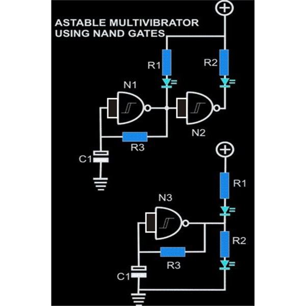
An astable multivibrator is an electronic configuration that generates continuous alternating high and low pulses from two outputs operating in tandem. The IC 4093 consists of four individual NAND gates in one package, specifically Schmitt trigger types, which provide...
The question sometimes comes up of how to cascade 4017 decade counters for more than 10 sequential stages. The LED sequencer below shows a possible solution using a few extra parts. When power is applied, the 15K resistor and...
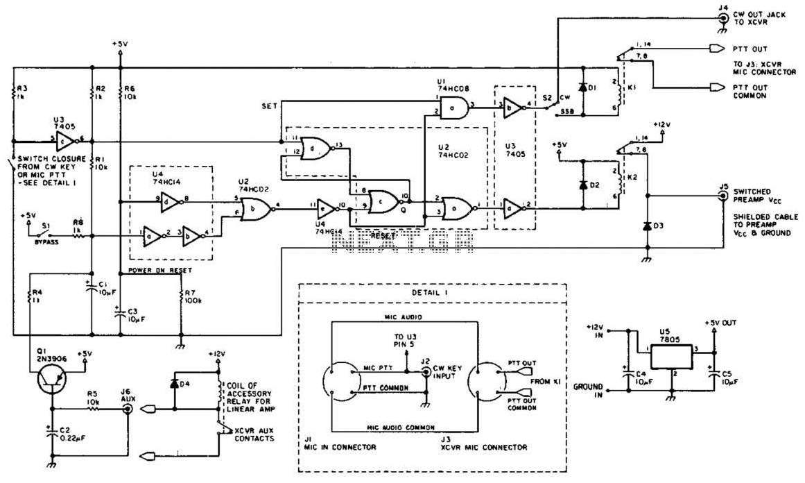
This circuit is beneficial for amateur radio operations in VHF and UHF frequencies, where a mast-mounted antenna preamplifier is employed for reception. The kit manages the transmit-receive (T-R) switching and relay sequencing to prevent high RF levels from being...
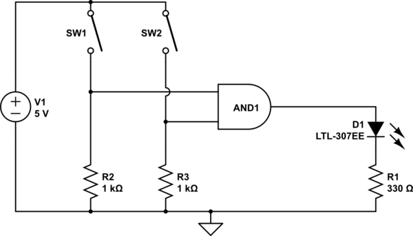
The AND output will be high when both switches are closed. However, there is no assurance regarding the input levels when the switches are open, resulting in unpredictable outcomes. In an electronic circuit utilizing an AND gate, the operation is...
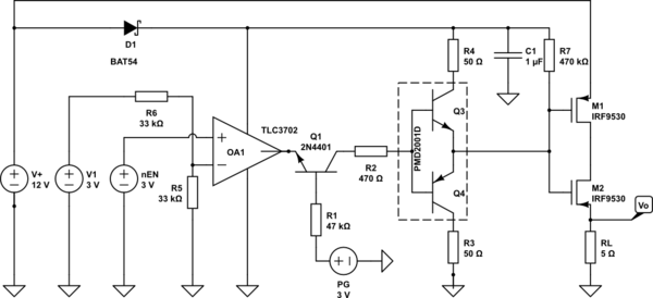
A battery switch-over circuit is being developed, consisting of two parallel lanes as depicted in the circuit diagram. The operational voltage range spans from 3V to 12V. Only one lane should be active at any given time, which is...
Warning: include(partials/cookie-banner.php): Failed to open stream: Permission denied in /var/www/html/nextgr/view-circuit.php on line 713
Warning: include(): Failed opening 'partials/cookie-banner.php' for inclusion (include_path='.:/usr/share/php') in /var/www/html/nextgr/view-circuit.php on line 713