
Geiger Counter I Circuit
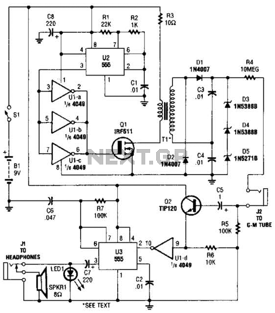
The output from T1, approximately 300 V, is processed through a voltage doubler (comprising D1, D2, C3, and C4), resulting in an output voltage of around 600 V. Three series-connected Zener diodes (D3, D4, and D5) are placed across the output of the voltage doubler to regulate the output to 500 V, which is then supplied through R4 (a 10-ohm current-limiting resistor) and J2 to the anode of the GM tube. This limiting resistor also facilitates the quenching of ionization detection. The cathode side of the tube is grounded via a 100-kΩ resistor, R5. When a particle is detected by the GM tube, the gases inside ionize, generating a pulse across R5. This pulse is further processed through C5 and applied to the base of Q2 (a TIP120 NPN transistor), where it is amplified and clamped to 9 V. The output from Q2 is inverted by gate U1-d and subsequently used to trigger U3 (the second 555 timer, configured for monostable operation). The output from U3 at pin 3 causes LED1 to flash and produces an audible click through speaker SPKR1 or headphones. The circuit is powered by a 9-V alkaline battery and consumes approximately 28 mA when idle, without detecting radiation.
The described circuit serves as a radiation detection system utilizing a Geiger-Muller tube to sense ionizing radiation. The astable configuration of the first 555 timer (U2) generates a continuous series of pulses that control the operation of the inverter and the subsequent transistor stages. The output pulses from the inverters effectively drive the transistor Q1, which in turn energizes the transformer T1, stepping up the voltage significantly for the detection circuitry.
The voltage doubler circuit, composed of diodes and capacitors, plays a crucial role in elevating the voltage to the necessary levels for the Geiger-Muller tube operation. The inclusion of Zener diodes ensures that the output voltage remains stable at 500 V, which is critical for the ionization process within the GM tube. The current-limiting resistor (R4) is essential for protecting the tube from excessive current, allowing for accurate detection of radiation events.
When ionizing radiation interacts with the GM tube, it causes a brief ionization event that generates a pulse detectable across R5. This pulse is then amplified by the TIP120 transistor (Q2), which acts as a signal conditioner, ensuring that the output is suitable for triggering the subsequent monostable timer (U3). The monostable configuration of U3 produces a single output pulse in response to the trigger from Q2, which activates the LED and the audio output, providing both visual and auditory feedback of radiation detection.
The entire circuit operates from a 9-V battery, ensuring portability and ease of use in various environments. The design emphasizes low power consumption, drawing only 28 mA when idle, which is beneficial for battery-operated devices. This combination of components and configurations results in an effective and reliable radiation detection circuit suitable for various applications in safety and monitoring. The circuit is built around a 4049 hex inverter (Ul), a pair of 555 osciliator/timers (U2 arid U3), two transistors, a Geiger-Muller tube, and a few additional support components. The first 555 (U2) is configured for astable operation. The output of U2 (a series of negative-going pulses) at pin 3 is fed to three parallel-connected inverters (Ul-a, Ul-b, and Ul-c).
The positive-going output pulses of the inverters are fed to the gate of Ql, causing it to toggle on and off. The output of Ql, which is connected in series with the primary of step-up transformer Tl, produces a stepped-up series of pulses in Tl`s secondary.
The output of Tl (approximately 300 V) is fed through a voltage doubler (consisting of Dl, D2, C3, and C4), producing a voltage of around 600 V Three series-connected Zener diodes (D3, D4, and D5) are placed across the output of the voltage doubler to regulate the output to 500 V, fed through R4 (a 10- current-limiting resistor) and J2 to the anode of the GM tube. The limiting resistor also allows the detection ionization to be quenchcd. The cathode side of the tube is connected to ground through a 100-kQ resistor, R5. When a particle is detected by the GM tube, the gases within the tube ionize, producing a pulse across R5.
That pulse is also fed through C5 and applied to the base of Q2 (a TIP120 npn transistor), where it is amplified and clamped to 9 V. The output of Q2 is inverted by gate Ul-d, then it is used to trigger U3 (the second 555, which is configured for monostable operation).
The output of U3 at pin 3 causes LED1 to flash, and produces a click that can be heard through speaker SPKR1 or headphones. The circuit is powered by a 9-V alkaline battery and draws about 28 mA when not detecting radiation. 🔗 External reference
Related Circuits

The thermostat electric circuit operates as depicted in the figure. It has three settings: off, low power (Lo), and high power (Peru HL). When the DIP switch SA is set to the Lo position, 220V AC is directed through...
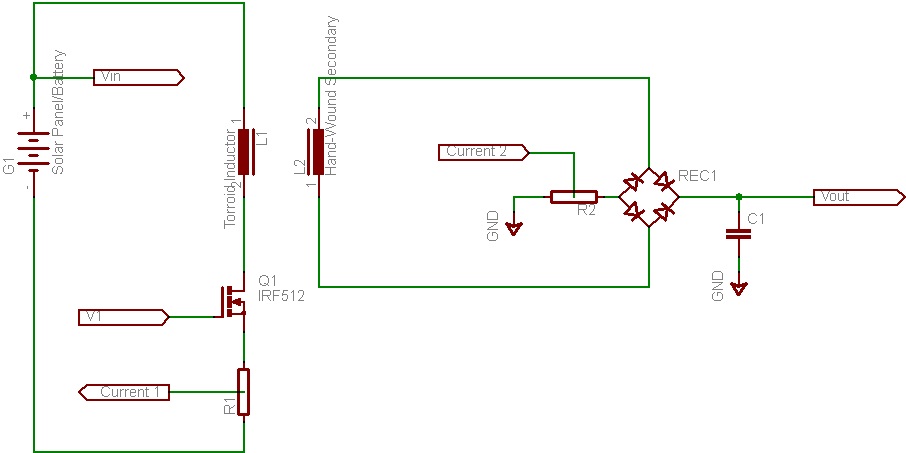
This document discusses the future direction of the Free Charge Controller project and proposes a new solar charge controller circuit. The Free Charge Controller project aims to enhance the efficiency and effectiveness of solar energy management systems. The proposed solar...
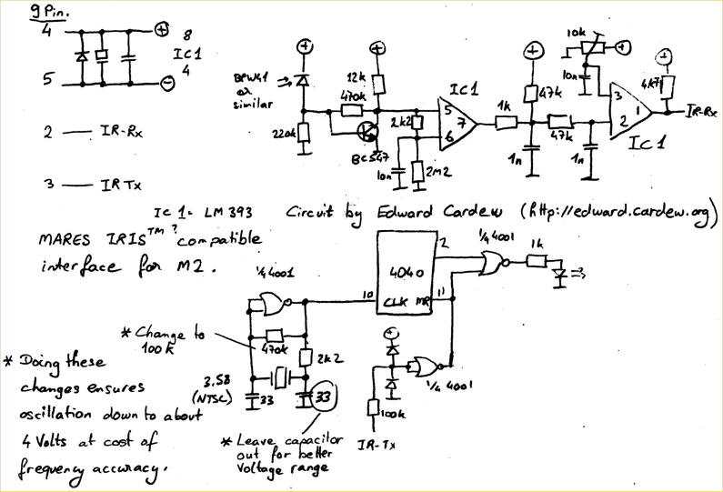
A TSOP4156 is often difficult to obtain or expensive to purchase. In response, an individual utilized old BPW41 infrared diodes to construct a custom receiver. The power source is derived from the RS232 port, requiring a minimum of 5.5...
The device employs a microammeter with a full-scale deflection of 50 µA and a resistance of 2 kilohms. The upper limit of the voltmeter's measuring range is 1 V, and within the range of 0.2 to 1 V, the...
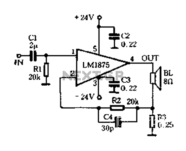
A current-sense amplifier is utilized to enhance the performance of the LM1875 current-mode amplifier circuit, as depicted in Figure 5-20. The resistor R3 and the series resistance of the speaker contribute to the current flowing through R3. This current...
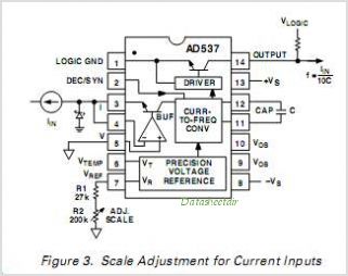
The AD650 is a voltage-to-frequency (V/F) and frequency-to-voltage (F/V) converter that offers high-frequency operation and low nonlinearity, features that were previously unavailable in a monolithic form. Its inherent monotonicity in the V/F transfer function makes the AD650 suitable for...