
Bridge Rectifier
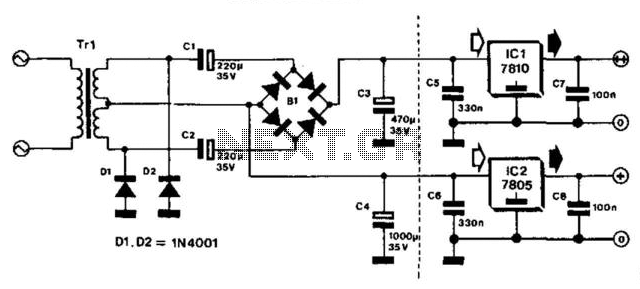
This bridge circuit effectively addresses the need for dual voltage outputs in various electronic applications. The use of a transformer with symmetric windings is critical, as it allows for the generation of two distinct voltage levels while maintaining balance in the system. The half-wave rectification process applied to one of the windings ensures that the lower voltage is efficiently extracted without excessive loss.
The integration of electrolytic capacitors serves a dual purpose: they not only provide electrical isolation between the two voltage outputs but also stabilize the output voltages by smoothing out fluctuations caused by load changes. This is particularly important in applications where voltage stability is crucial for the operation of sensitive electronic components.
The bridge rectifier configuration further enhances the circuit's efficiency by converting the alternating current (AC) from the transformer into direct current (DC), suitable for powering DC loads. The design ensures that the transformer operates within its optimal capacity, as the equal current flow through both windings minimizes the risk of overheating and prolongs the lifespan of the transformer.
In terms of load management, the lower voltage supply's capacity is primarily determined by the transformer's specifications, while the higher voltage supply's output is influenced by the reactance of the capacitors involved. This reactance, denoted as Xh r 50 C, plays a critical role in establishing the maximum load that can be safely drawn without compromising voltage stability.
Overall, this bridge circuit exemplifies a well-engineered solution for applications requiring dual voltage supplies, balancing efficiency, and performance while minimizing potential drawbacks associated with voltage regulation and transformer loading. This bridge circuit is intended for those cases where two unequal supply voltages are required. The lower voltage is obtai ned with the aid of a transformer with symmetric windings and half-wave rectification of the potential across one winding. For the higher voltage, the potential across both windings is rectified. To that end, the output of the transformer is linked to the bridge rectifier via two electrolytic capacitors that provide isolation of the two direct voltages.
A bonus with this type of circuit is that although the two supplies can be loaded unequally, the currents through the two transformer windings are the same. Thus, the transformer is loaded symmetrically so that its full capacity can be used. Moreover, no unnecessary dissipation is in the voltage regulators. The load on the lower voltage supply depends primarily on the rating of the transformer. The load on the higher voltage supply is limited by the reactance of Cj and C2 (= xh r 50 C) and the required minimum output voltage.
🔗 External reference
Related Circuits
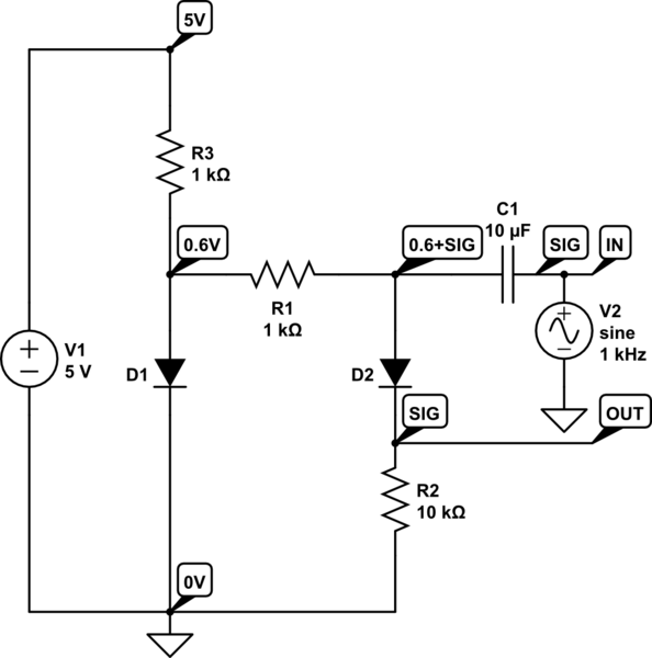
D1 compensates for the forward voltage drop of D2 by providing a 0.6V bias. The +5V is an external source. D1, R1, and R3 create a 0.6V bias on the capacitor's other side, allowing a positive signal swing to...
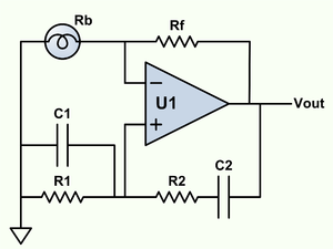
Wien bridge oscillator. A phase-shift feedback oscillator that uses a Wien bridge as the basis for its operation. The Wien bridge oscillator is a type of electronic oscillator that generates sine waves. It operates based on the principle of phase...
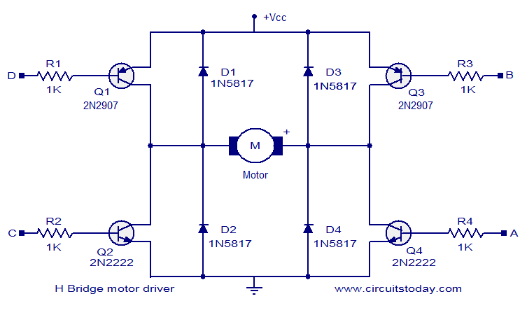
The circuit presented is a simple H-bridge motor driver circuit utilizing commonly available components. An H-bridge is an efficient method for driving motors and is widely used in various electronic projects, particularly in robotics. The circuit illustrated is a...
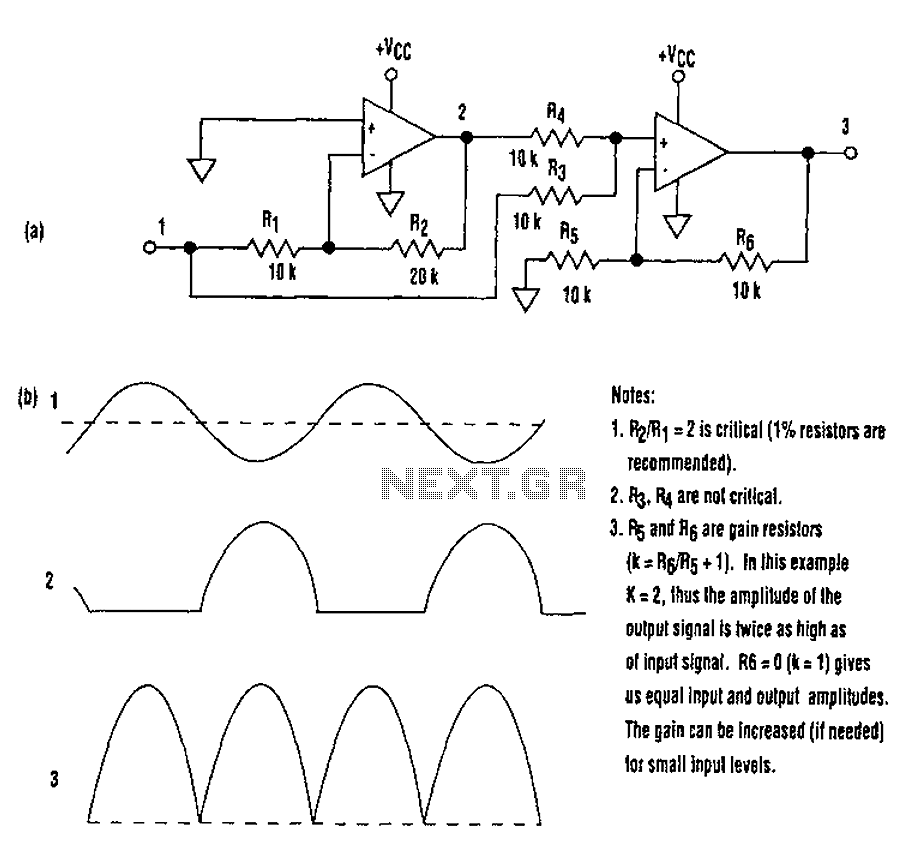
When utilizing a single-supply operational amplifier in a bipolar signal environment, achieving simple functions can be challenging. This often necessitates the inclusion of additional operational amplifiers and other electronic components. The advantages of this configuration can be observed in...
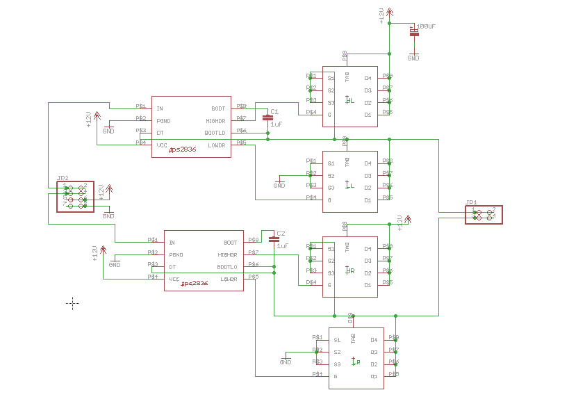
An H-bridge circuit was constructed using the TPS2836 and CSD16404 components. The schematic is provided below. However, the circuit is not functioning correctly, leading to several inquiries regarding potential design flaws. The power supply voltage (VDD-GND) is set to...
The opto-isolator LEDs are connected to three wires labeled "FWD," "REV," and "ENA." These wires serve as the interface between the bridge and the microprocessor. It is important to note that there is no "ground" signal present. When connecting...
Warning: include(partials/cookie-banner.php): Failed to open stream: Permission denied in /var/www/html/nextgr/view-circuit.php on line 713
Warning: include(): Failed opening 'partials/cookie-banner.php' for inclusion (include_path='.:/usr/share/php') in /var/www/html/nextgr/view-circuit.php on line 713