
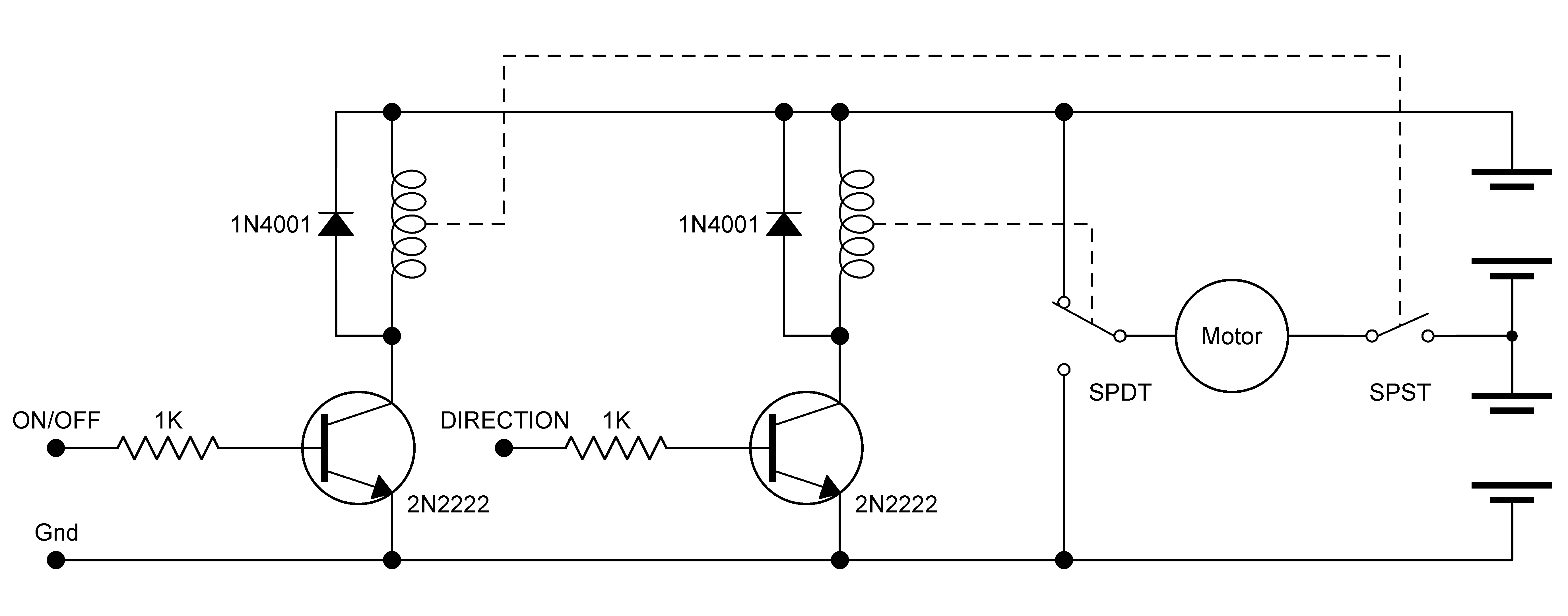
h bridge with pwm
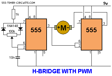
The described circuit employs an H-bridge arrangement, which is essential for controlling the direction of the motor's rotation. The H-bridge consists of four switches (transistors or MOSFETs) arranged in a bridge configuration, allowing for the reversal of current through the motor. When the potentiometer is adjusted, it alters the duty cycle of the PWM signal generated by a microcontroller or a dedicated PWM circuit. This signal modulates the average voltage applied to the motor, effectively controlling its speed.
In the mid-position of the potentiometer, the PWM duty cycle approaches zero, resulting in no current flow to the motor and consequently halting its operation. As the potentiometer is turned in one direction, the PWM signal increases, allowing more power to reach the motor, thus increasing its speed in the designated direction. Conversely, turning the potentiometer in the opposite direction decreases the PWM duty cycle, reducing the motor's speed or reversing its direction.
The circuit includes current-limiting features to prevent damage to the motor and the H-bridge components, ensuring that the maximum current does not exceed 200 mA. This is particularly important for small motors that may experience stall conditions under load. Additionally, the use of a voltage rating below 6 V ensures safe operation and compatibility with low-voltage motors.
Overall, this circuit effectively demonstrates the principles of motor control using PWM and H-bridge technology, providing a versatile solution for applications requiring precise speed and direction control.This circuit drives a motor clockwise / anticlockwise via a pot and reduces the speed to zero when the pot is in mid-position. The current is limited to 200mA and the voltage across the motor is less than 6v, but the circuit shows the principle of Pulse Width Modulation (providing powerful bursts of current to the motor to create a high or low RPM
under load) and both forward / reverse RPM via the H-bridge arrangement. 🔗 External reference
Related Circuits
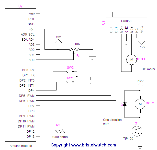
Connecting and programming the TA8050 DC motor controller with the Arduino microcontroller. The TA8050 is a versatile DC motor controller designed for use with microcontrollers, such as the Arduino. This controller allows for precise control of DC motors, making it...
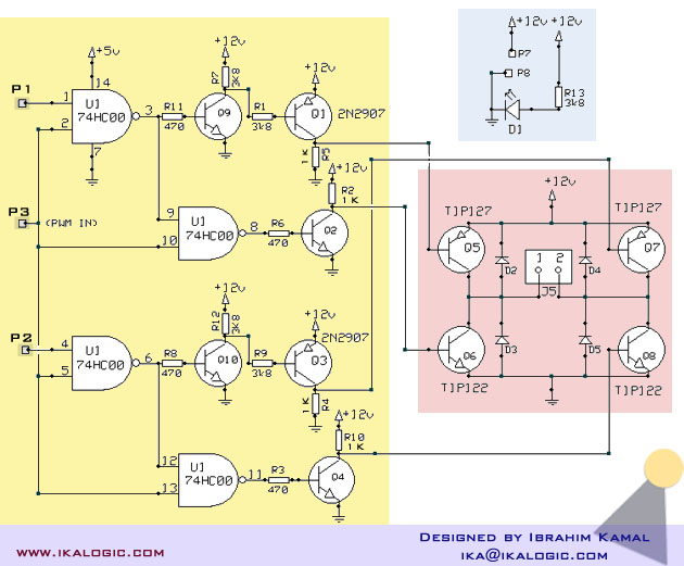
A relatively high-power H-bridge motor controller, which is a common method to control DC motors, utilizes inexpensive TIP transistors. A continuous current of 5 Amperes through an H-bridge module may not seem significant to some, depending on their background...
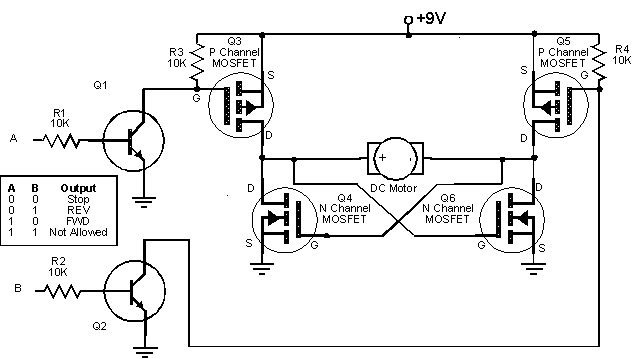
Create an H-Bridge for controlling a DC brushed motor using PWM. One bridge will control one DC motor. The bridge will have three inputs: A, B, and PWM. Inputs A and B will determine the direction of the motor,...
Three examples of Wien Bridge oscillators are shown below. The first uses three bipolar transistors. The second uses a bipolar and JFET, and the third is the more popular type using an op-amp for minimal parts. The idea is...
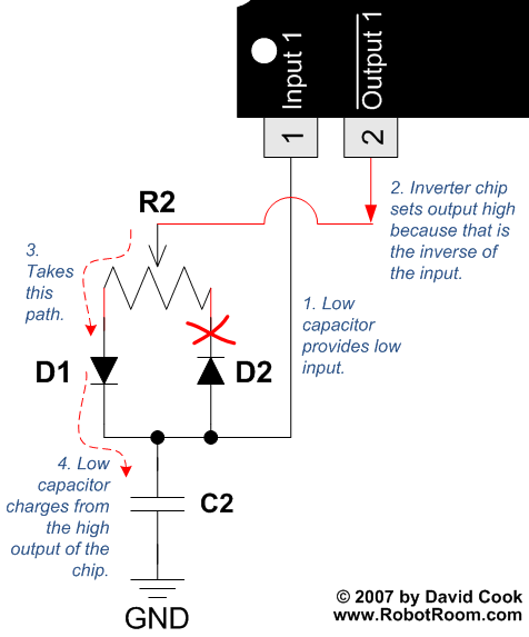
To understand how the 74AC14 PWM circuit functions, it is essential to focus on the schematic section that includes the trimpot, diodes, capacitor, and the first inverter logic gate. Initially, when power is applied to the circuit, the capacitor...
Bridges enable robots to control high-current motors by connecting the low-current logic circuitry of the robot's brain to the high current required by the motors. Many bridges utilize the common "H" arrangement of control circuitry, typically involving power transistors,...