
Half-wave rectifier
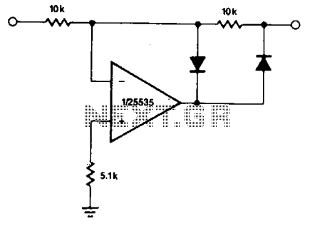
The described circuit functions as a half-wave rectifier, effectively converting alternating current (AC) signals into direct current (DC) signals by allowing only one polarity of the input signal to pass through. The gain characteristics indicate that when a positive voltage is applied, the output remains at zero volts, while a negative voltage results in an output that is the negative of the input signal. This behavior can be useful in applications where only the negative part of the signal is required or where signal inversion is necessary.
The inclusion of two diodes in the circuit allows for the reversal of polarity, providing flexibility in signal processing. However, it is essential to consider the output impedance, which may vary based on the input signal's polarity. This variation can impact the performance of subsequent stages in the circuit, making buffering a crucial consideration. A buffer stage can help stabilize the output impedance, ensuring that it remains consistent regardless of the input signal's characteristics.
The requirement for the output to transition through two diode drops when the input polarity reverses is also significant. This transition can introduce additional delay and distortion in the output signal, which must be accounted for in high-speed applications. The NE5535 operational amplifier, noted for its low distortion and high-frequency capabilities, is suitable for this circuit, as it can handle frequencies up to 10 kHz while maintaining distortion levels below 5%. This specification ensures that the rectification process remains accurate and reliable within the operational limits of the NE5535, making it an appropriate choice for various signal processing applications.The circuit provides for accurate half-wave rectification of the incoming signal. For positive signals, the gain is 0; for negative signals, the gain is -1. By reversing both diodes, the polarity can be inverted. This circuit provides an accurate output, but the output impedance differs for the two input polarities and buffering may be needed. The output must slew through two diode drops when the input polarity reverses. The^NE5535 device will work up to 10 kHz with less than 5% distortion. 🔗 External reference
Related Circuits
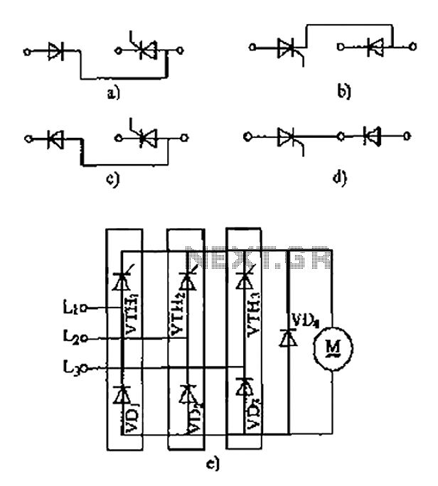
The thyristor linking arm rectifier module is a three-phase half-controlled bridge rectifier circuit. The thyristor-rectifier module linking arm consists of a thyristor and a rectifier diode connected in series or parallel, designed to fulfill specific requirements in power circuits....
The schematic illustrates how +25V DC and -25V DC are generated to supply power to two stereo amplifiers. An 80VA power transformer with a 240V/36V center-tapped secondary winding is utilized. The secondary output of the transformer is rectified using...
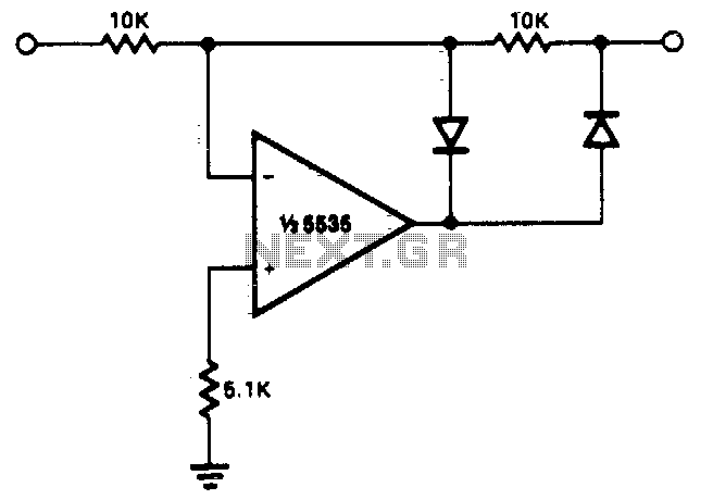
This circuit allows for precise half-wave rectification of the incoming signal. It exhibits a gain of 0 for positive signals and a gain of -1 for negative signals. By reversing the orientation of both diodes, the output polarity can...
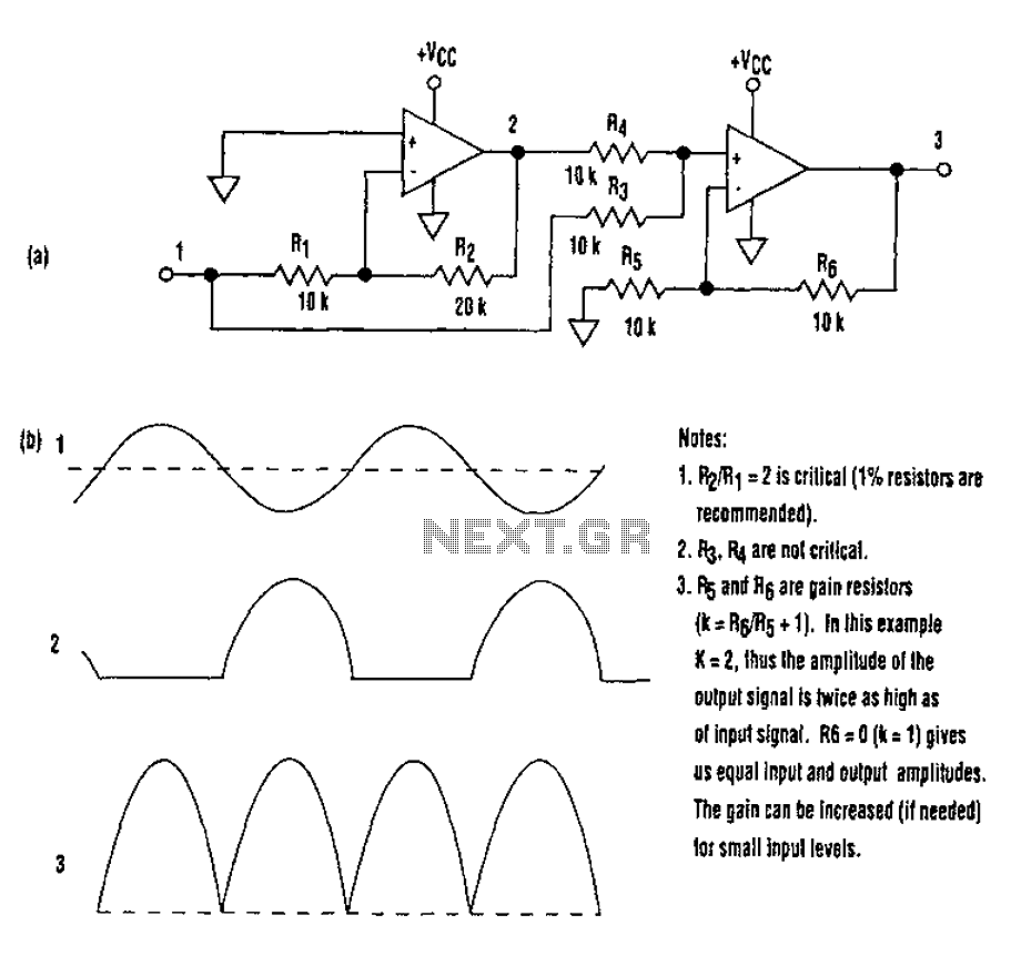
When utilizing a single-supply operational amplifier in a bipolar signal environment, achieving simple functions can be challenging. This often necessitates the inclusion of additional operational amplifiers and other electronic components. The advantages of this configuration can be observed in...
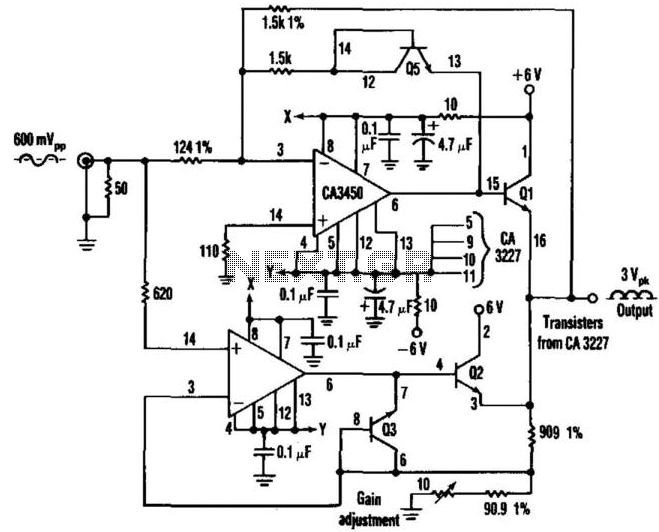
This circuit employs two CA3450 operational amplifiers and a CA3227 transistor array to achieve accurate full-wave rectification of signals up to 10 MHz. Two of the CA3227 transistors are responsible for driving the output, while the other two are...
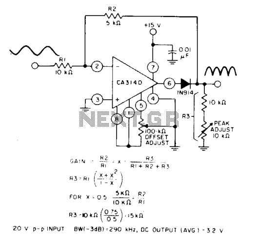
When the equality of two equations is satisfied, the full-wave output of the circuit is symmetrical. The circuit utilizes a CA3140 BiMOS operational amplifier in an inverting gain configuration. The circuit design featuring the CA3140 BiMOS operational amplifier is characterized...