
HandyBoard 16 servo addon and software
The circuit design effectively expands the capabilities of the handyboard by integrating additional servo control through a modified architecture. The implementation of the 4514 IC allows for efficient management of multiple servos, enabling precise positional control through pulse width modulation (PWM). The use of the 68HC11 microcontroller provides the necessary timing and control logic, ensuring that servo positions can be accurately maintained based on the defined pulse durations. The choice of using a bi-directional timer pin on the 68HC11 enhances the flexibility of the design, allowing for real-time monitoring and control of the servo positions.
The integration of the L293D motor driver facilitates the handling of the motor outputs, while the 374 latch provides a means to store and manage the control signals effectively. This design approach allows for a scalable solution, where additional servos can be added without significant redesign, simply by utilizing the existing architecture of the 4514 decoder and the associated motor control circuitry.
In terms of performance, the design adheres to the operational limits of the servo motors, ensuring that pulse timings remain within acceptable ranges to prevent signal degradation or servo malfunction. The careful consideration of the timing and control logic ensures that the system operates efficiently, with minimal latency between servo commands. The overall circuit design demonstrates a robust solution for multi-servo control applications, suitable for various robotics and automation projects.The expansion board had 6, but I didn`t think that 6 servo ports were worth the price of the expansion. I ended up making a fully reversible modification to my handyboard that gave me 16 servo ports costing a total of about $2, two of the motor ports and a digital input.
Aservo motor doesn`t just turn when we apply voltage. instead, it is a positional motor - it exerts effort to maintain a particular position. We tell it which position by supplying a string of pulses, where the time that the pulse is positive defines the position we want the motor to hold. 0. 8ms is 90 degrees left, 1. 5ms is center, and 2. 2ms is 90 degrees to the right. Digital input #9 is connected to a special pin on the 68HC11. It is connected to a bi-directional timer pin which can have its digital level read, throw an interrupt when it changes and record the time, be a digital output, or make a pulse that goes for a specific length of time (of either polarity), and throw an interrupt when the pulse ends!
I did a little bit of maths, and worked out that this timer has a resolution (or accuracy) of 500ns! this means 3, 000 counts for center position - well within our maximum time of 65, 535 counts. The fact that we can ask the 68hc11 to tell us when its done is great too - we can use this to trigger the pulse again without ever having to check if we need to start again! Instead of making the board wait until its ok to pulse again, I wondered if I could get it to pulse a different servo in that time instead - enter the 4514 ic.
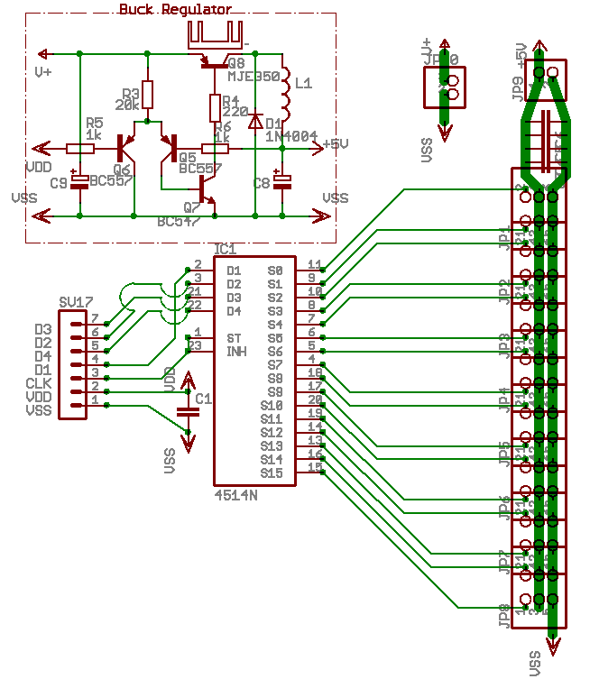
The 4514 ic basically decodes 4 bits and sends the relevant one of 16 pins positive. Each motor port uses two bits - direction and enable. I decided that I wouldn`t need more than two motor ports, and could use the other two to talk to the 4514. The signals to the L293D are latched in the `374 next to them, which means that if we remove one L293D, we have four bits that we can program to do anything we want.
The four signals to the L293D chip are present on pins 1, 2, 9 and 10. (the two direction signals are also available inverted on pins 7 and 15, but they`re not much use to us here. ) If we connect these four pins to the 4514`s A, B, C and D inputs, along with ground and 5v, we should be able to programatically make any of the 4514`s 16 outputs go positive!
The 4514 also has an INHIBIT input that, when driven positive will make all 16 outputs negative. If I connected this line to my timed pulse pin, I could select a servo using the motor port, pulse it with the timer, and then select the next servo and repeat. 16 servo pulses at 2. 2ms is about 40ms all up - which is just within the dead zone tolerance of most servos. 16 pulses at 0. 8ms is about 12ms which is cutting it fine, but acceptable. I pulled out the bottom L293D, and wired in the 4514 according to my plan with some pin headers from an old pc/isa super IO board, and wrote some software to control it.
After I had debugged my program, I went for a test with 12 servos plugged in. They all went crazy! Something was seriously wrong somewhere, but what was important at the time was They were all moving! I probed around with my logic probe, and scanned through my code, and then the IC library code to try and work out what was going on.
After much hair-pulling exasperation, I finally worked out that the PWM code for the motors kept running even if the motor was off. You guessed it, the IC library`s system interrupt that provides you with that nice heartbeat was re-selecting the servo every time around the loop.
I did try hacking at the library, but eventually noticed a much easier way to do it. The 4514 has 24 pins. 2 for power, 4 inputs, 16 outputs is 22, the INHIBIT line is 23, but what was the 24th pin I had a look. The pin was marked STROBE, and a footnote in the manual said that this pin had to be positive for the chip to accept new inp
🔗 External reference
Related Circuits
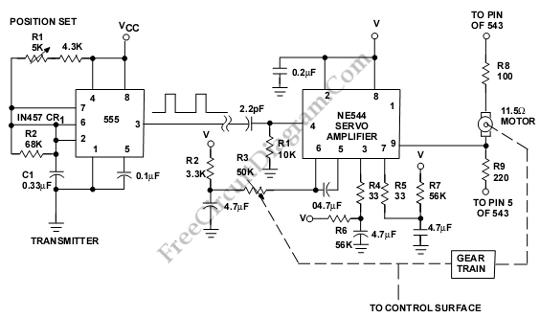
This is a servo system controller circuit designed for remote control of a servo motor. The circuit utilizes a 555 timer and requires only six additional components. The servo system controller circuit operates by generating a pulse-width modulation (PWM) signal,...
The servo motor has numerous applications in various fields, including robotics, puppetry, photography, and more. These compact motors can accurately position their output shaft to any specified angle and maintain that position. Most servos have a motion range of...
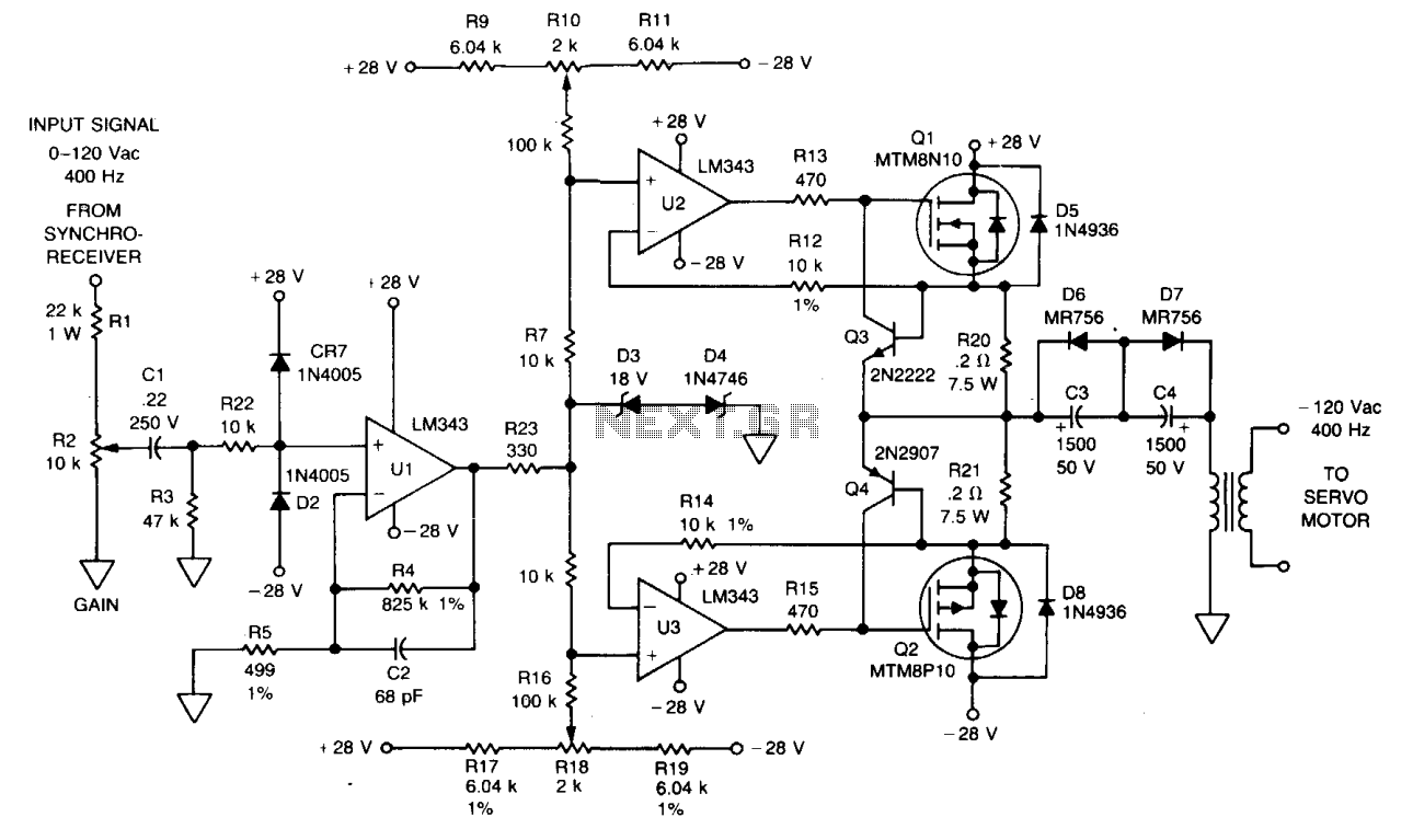
The signal from a synchro receiver or a variable resistive cam follower (potentiometer) is amplified by operational amplifier U1, with its output swing constrained by back-to-back Zener diodes D3 and D4. This amplified signal is then fed into operational...
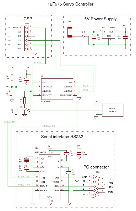
A servo controller designed to control a servo motor via a serial port using a PIC microcontroller. The project encompasses both source code details and schematic diagrams. The servo controller operates by interfacing a PIC microcontroller with a servo motor,...
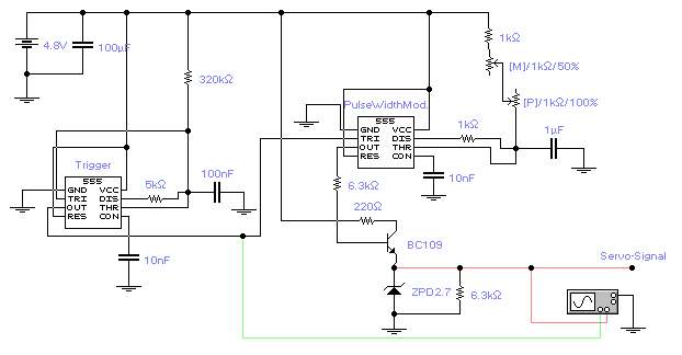
The first timer IC555 generates a negative trigger signal with a frequency of approximately 45Hz, producing a trigger impulse every 22ms. It is important not to exceed 50Hz for optimal servo performance. The second timer IC555 produces a modulated...
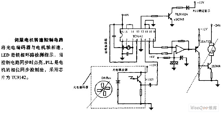
The servo motor speed control circuit connects the photoelectric encoder to the motor shaft. The LED serves as an indicator light for the phase-locked loop (PLL) detection, illuminating when the control circuit is synchronized. The PLL employs a phase...