
Hard but soft power switch for Arduino
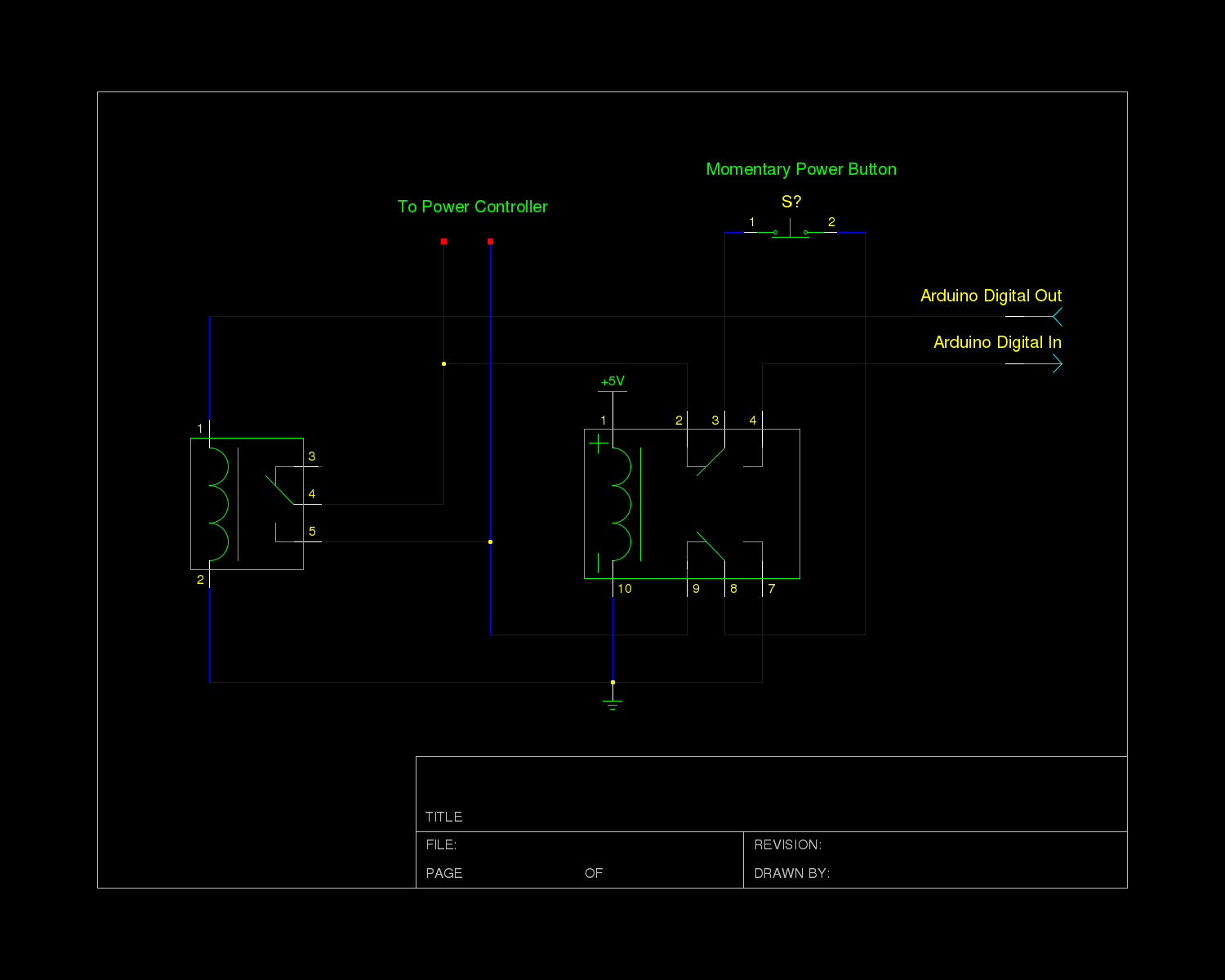
This configuration allows the button to connect to the power controller when the system is off (i.e., when no 5V power is available) and to connect to the Arduino inputs once the system is powered on. The relay's physical switching between circuits eliminates concerns about the different operating voltages of 12V and 5V. In the schematic, it is assumed that the Arduino's input pin has its internal pull-up resistor enabled. Additionally, it is presumed that the relay can be driven directly by the Arduino, although this is not always feasible; a transistor may be required to drive the relay. It is important to note that this circuit remains untested and should be used at the user's own risk.
The power controller module is designed to manage the power supply to the system's transformers efficiently. The integration of a momentary switch allows for user-friendly operation while ensuring that the system can be powered down safely after configurations are made. The choice of a DPDT relay facilitates seamless switching between the controller and the Arduino, thereby enhancing the flexibility of the design.
The relay's operation is crucial, as it determines the connection between the momentary switch and the respective circuits based on the system's state. When the system is powered off, the relay connects the momentary switch to the power controller, enabling the user to turn on the system. Conversely, when the system is powered on, the relay redirects the switch's connection to the Arduino, allowing it to monitor button presses for further functionality, such as initiating shutdown procedures or other programmed responses.
The schematic should include the necessary components: a momentary switch, a DPDT relay capable of handling the voltage and current requirements, the Arduino microcontroller, and any additional components such as resistors and transistors needed for driving the relay. Proper attention must be given to the relay's specifications, ensuring it can handle the switching requirements without failure. Additionally, the design should consider safety protocols when dealing with mains power, including appropriate fusing and isolation techniques to protect both the user and the circuitry.The power controller module used in the system takes input directly from a momentary switch and uses that to toggle a relay that passes mains power to the system’s transformers. The controller circuit operates at 12V and as I understand was chosen to allow a wider variety of fancy lower voltage buttons and power LEDs to be used.
Getting the Arduino to act as a momentary switch (via transistors or relays) works fine for powering the unit down once settings have been saved. However, the actual physical power switch needs to work directly with the controller when the system is off, but talk only to the Arduino when the system is on.
To do this, we decided to hook the power button up through a DPDT relay that is switched directly by the 5 volt supply. This way, the button is connected to the power controller when the system is off (ie. no 5 volt power is present) and then once the system is on, the button is connected to the inputs on the Arduino. Since the relay physically switches the button between circuits, it doesn’t really matter that one circuit operates at 12 volts and the other at 5.
In my schematic, I assume that the input pin on the Arduino has the internal pull up resistor activated. I also assume that the relay can be driven directly by the Arduino, which often isn’t the case. You will likely need to use a transistor to drive the relay. Note that thus far the circuit is untested and should be used at your own risk. 🔗 External reference
Related Circuits
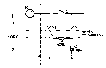
Closing the switch S allows the AC positive half-cycle to flow through diode VDI and resistor R, causing the SCR to open simultaneously at both ends of the capacitor C, which becomes fully charged. During this phase, the positive...
.jpg)
The HID ballast circuit consists of a buck stage for regulating lamp current and power, a full-bridge output stage that generates a low-frequency (200Hz) AC square-wave voltage and current to drive the lamp, and an ignition circuit that produces...
Access to the resistors was available, and measurements indicated an open circuit when disconnected from any ground or input source. The circuit in question involves resistors that have been verified for accessibility. When measured in isolation—meaning they are not connected...
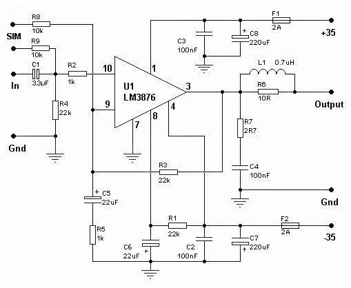
The amplifier drives a pair of speakers using two LM3876 amplifier chip circuits (50 watts per channel) or a pair of headphones with Meier Crossfeed through a clarifier and a dual OPA2134 Opamp. It features four selectable band inputs...
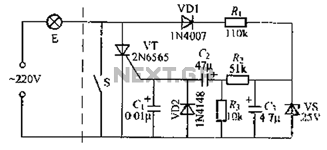
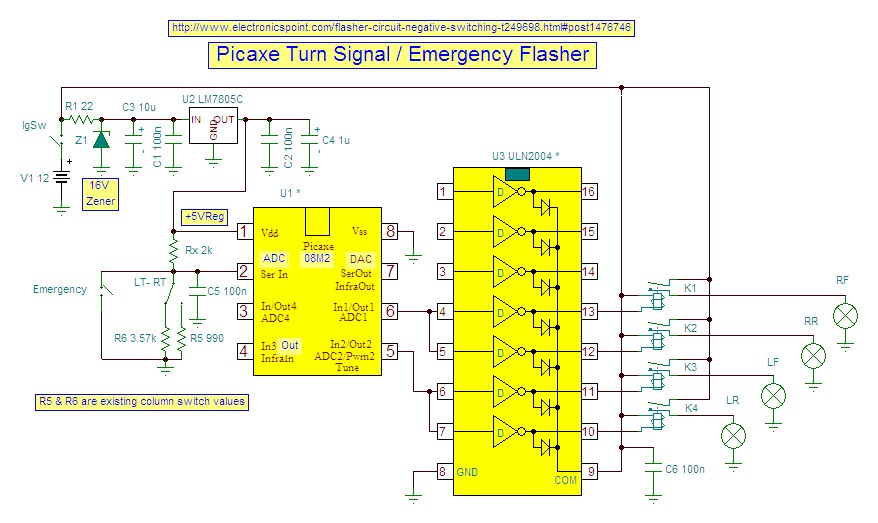
A delay circuit using an improved quenching lamp pull switch is described, focusing on its performance and the delay function in lighting control. The circuit exhibits a high degree of stability and reliability. When switch S is closed, the...
This circuit will provide a negative DC voltage that is approximately equal to the positive input voltage at no load and about 3 V less at a 10 mA load. The input voltage range is from +5 to +15...