
Hartley Oscillator Calculator

The inductive three-point oscillator circuit is a specialized configuration that leverages the characteristics of inductors and capacitors to generate oscillations. The circuit comprises a transistor (Q), two inductors (L1 and L2), and a capacitor (C) that together form a resonant LC circuit. The feedback mechanism is critical for sustaining oscillations; L2 not only participates in the resonant circuit but also acts as a feedback network, providing necessary voltage to the base of the transistor through the coupling capacitor (Cb).
The design allows for the creation of a communication channel, where the resonant circuit connects three distinct endpoints, each associated with a transistor. This arrangement enables efficient signal transmission and amplification, making it suitable for various applications in communication systems.
In terms of performance, the high-Q characteristic of the circuit ensures that the oscillation frequency remains closely aligned with the resonant frequency of the LC circuit. The relationship is defined by the formula governing LC resonant circuits, which indicates the frequency at which the circuit naturally oscillates. However, while the three-point oscillator is adept at initiating oscillations, the output waveform quality can be suboptimal.
This degradation arises from the feedback voltage that is influenced by the inductance at both ends of the inductor. At higher frequencies, the impedance of the inductance increases, which can introduce additional harmonic components into the feedback signal. As a result, the output waveform not only reflects the fundamental frequency but is also populated with high harmonics, which can distort the signal and affect the overall performance of the circuit.
In summary, the inductive three-point oscillator circuit is a complex yet effective design that exemplifies the interplay between inductance, capacitance, and feedback mechanisms in generating oscillations, albeit with certain trade-offs in output waveform fidelity.Q is the transistor, L1, L2, C resonant circuit formed, L2 double as feedback network, through the coupling capacitor Cb will be sent to feedback voltage transistor base. Figure 2 shows the communication channel, resonant circuit with three endpoints and the three most connected transistor, it is known as the inductive three-point oscillator circuit, also known as feedback oscillation circuit inductance.
When a high-Q circuit, the circuit`s oscillation frequency essentially equal to the resonant frequency of LC circuit, the formula is as follows: Inductance characteristics of three-point oscillator circuit is easy to start oscillating, but its output waveform is poor, due to feedback voltage from both ends of the inductor, while the inductance of the high harmonics of the impedance of a larger, and thus contains the feedback voltage more harmonic components, therefore, the output waveform also contains more high harmonics. 🔗 External reference
Related Circuits
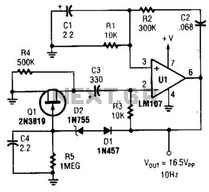
This Wien-bridge sine-wave oscillator utilizes a 2N3819 as an amplitude stabilizer. The 2N3819 functions as a variable-resistance element within the Wien bridge. The Wien-bridge oscillator is a type of electronic oscillator that generates sine waves. It employs a bridge circuit...
An idea proposed is to utilize a phase shift oscillator followed by an inverter to convert a sine wave into a square wave; however, this may be considered a rudimentary solution. There is also interest in schematics for a...
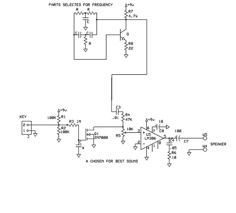
A schematic for a code practice oscillator is needed, which can be connected to a keyer. The desired setup involves using a Picokeyer, allowing the oscillator to be plugged into the key jack of the Picokeyer. The output should...

This circuit represents a negative resistance configuration. All previous circuits utilize RC time constants to achieve resonance. LC combinations can also be employed, providing good frequency stability, high Q factor, and rapid startup. In this circuit, a signal input...
The Oscillator Design Guide is integrated into Agilent EEsof's Advanced Design System environment, functioning as a smart library and interactive handbook for creating effective designs. It enables quick oscillator design, interactive characterization of components, and provides in-depth insights into...
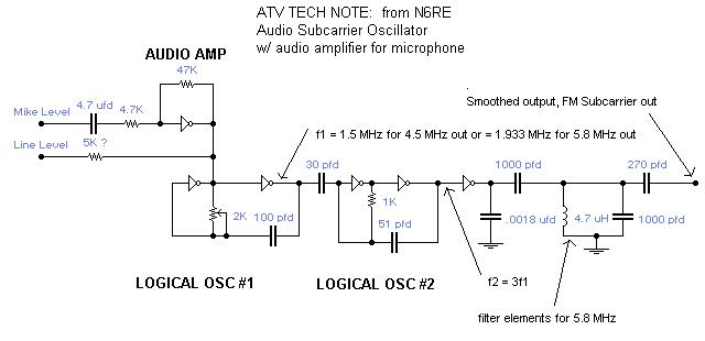
A single integrated circuit (IC) provides all amplifiers: the 74HC04 Hex Inverter, which is a digital component. The second oscillator synchronizes to three times the frequency of the first oscillator, thereby tripling the frequency modulation (FM) deviation. Utilizing the...