
HiFi preamp with tone control
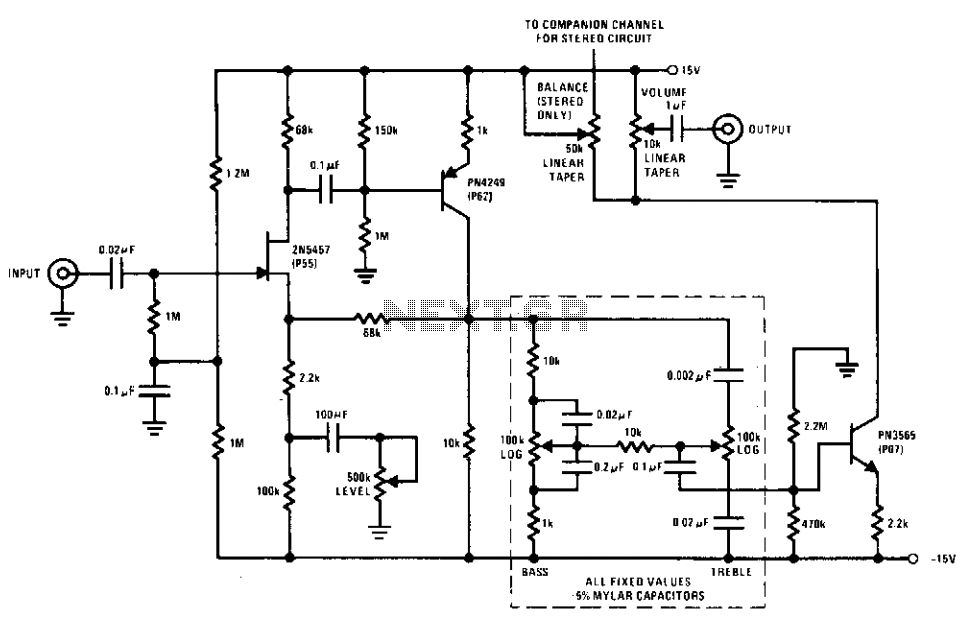
The circuit design features a JFET (Junction Field-Effect Transistor) as the primary amplifying element, chosen for its low noise characteristics and high input impedance, making it ideal for processing weak signals without introducing significant distortion. The JFET operates in the linear region, ensuring that the signal integrity is maintained throughout the amplification process.
The tone control section incorporates adjustable resistive and capacitive elements, allowing for precise manipulation of frequency response. The capability to achieve an 18 dB cut or boost enables users to tailor the audio output to their preferences, accommodating various audio sources and listening environments.
The amplifier stage is designed to provide a robust output, capable of delivering 1 V for a 100 mV input signal at maximum gain. This high level of output ensures compatibility with a wide range of audio equipment, facilitating seamless integration into existing audio systems. The low harmonic distortion level of less than 0.05% is indicative of high fidelity performance, ensuring that the audio signal remains clean and true to the original source.
Overall, this preamp and tone control circuit is engineered to deliver exceptional audio quality, characterized by low noise, minimal distortion, and versatile tone shaping capabilities. Its design emphasizes reliability and performance, making it suitable for both professional and consumer audio applications.This preamp and tone control uses the JFET to its best advantage; as a low noise high input impedance device. All device parameters are noncritical, yet the circuit achieves harmonic distortion levels of less than 0.05% with a S/N ratio of over 85 dB.
The tone controls allow 18 dB of cut and boost; the amplifier has a 1-V output for 100-mV input at maximum level. 🔗 External reference
Related Circuits
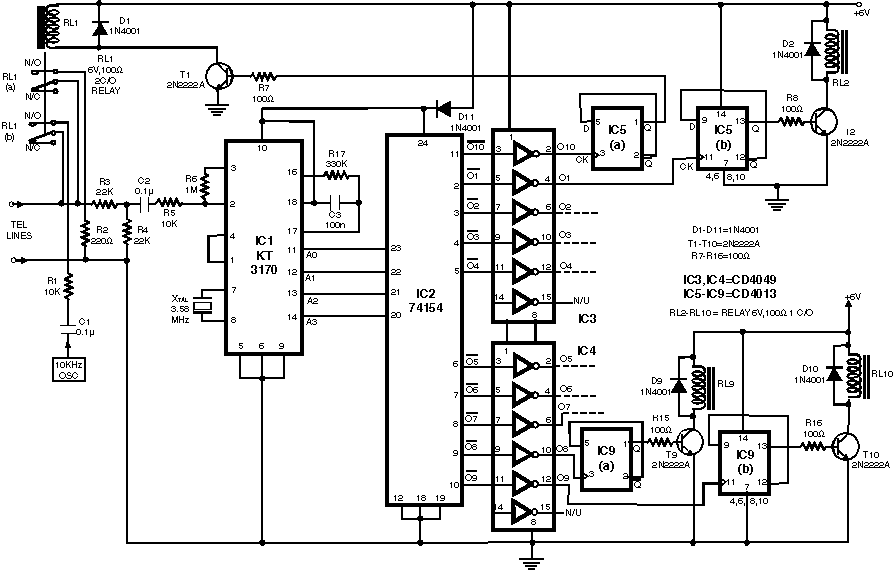
This circuit illustrates a remote control system utilizing a radio telephone circuit diagram. Features include the ability to switch appliances from any distance, overcoming various limitations. The remote control circuit employs radio frequency (RF) technology to facilitate wireless communication between...
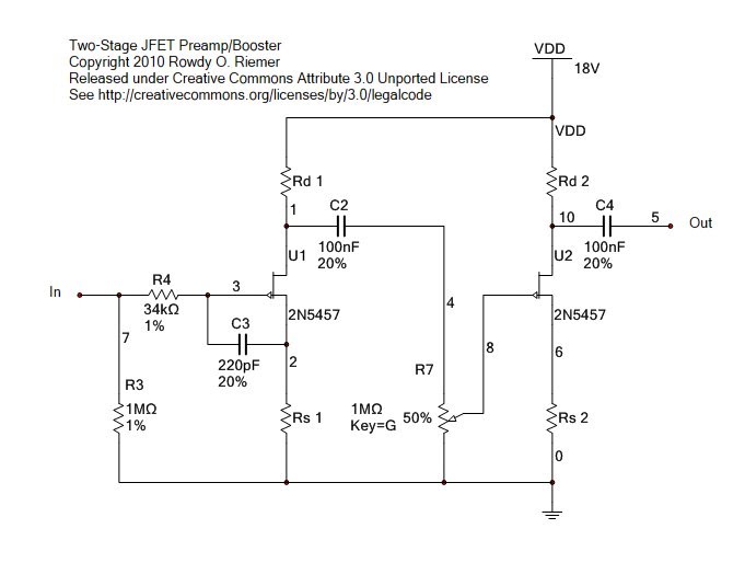
This circuit functions as a clean preamplifier or booster pedal. It is specifically designed for clean amplification rather than overdrive, although it can be overdriven to produce soft clipping typical of JFETs. The circuit originated as a booster pedal...
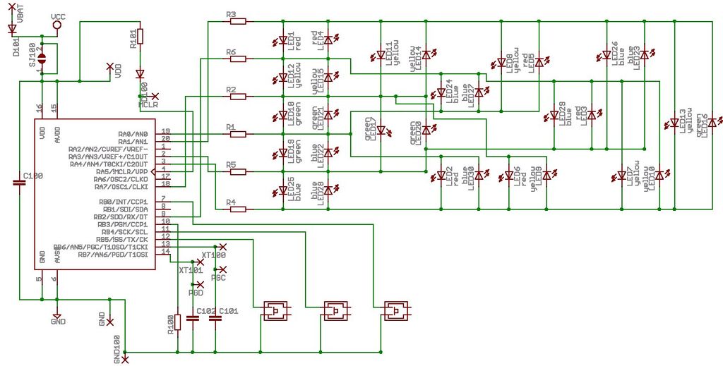
Microdot - wrist watch LED pattern timepiece. This project is a circuit board designed for creating a wristwatch-sized version. The Microdot wristwatch project involves the design and implementation of a compact circuit board that integrates LED technology to display time...
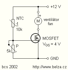
When the fan seized up in my source and I changed it to a type with much less noise, turned on my computer, the largest source of noise CPU cooler fan. The computer I have a boxed Pentium III...
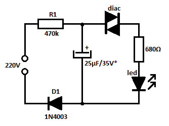
This is likely the simplest concept for generating a flashing light from an LED using alternating current (AC). The circuit provides a straightforward method for flashing one or more LEDs using high-voltage direct current (DC) sourced from mains electricity....
This transmitter can be utilized for multiple applications. An INS8048L microprocessor produces various codes based on keypad inputs. These codes are modulated onto a 40-kHz carrier frequency. Additionally, Q1 drives infrared LEDs LED1 and LED2. The transmitter circuit primarily consists...