
Two-Stage JFET Preamp/Booster
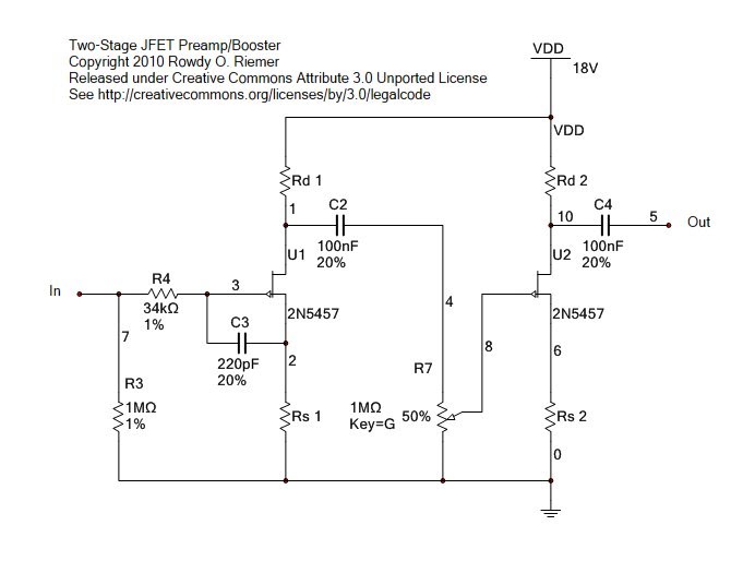
This circuit is intended primarily for use as a clean preamplifier or booster. It leverages low-noise JFETs, particularly the 2N5457, to achieve high gain with minimal distortion. The circuit is designed with a focus on headroom, allowing it to accommodate various guitar pickups without significant loss of signal integrity. The choice of an 18 V power supply is critical, as it maximizes the available clean gain while ensuring that the output remains within acceptable limits for most applications.
The circuit topology is based on the Fetzer Valve concept, which aims to emulate the characteristics of a vacuum tube amplifier. This is achieved through careful selection of resistors and capacitors that establish the biasing conditions for the JFETs. The omission of the source resistor bypass capacitor is a deliberate choice that limits the maximum gain per stage, aligning with the design's goal of maintaining clarity and preventing unwanted distortion.
The design incorporates a multi-stage amplification approach. The first stage includes a Miller capacitor to filter out RF interference, while the second stage is optimized for frequency response without the capacitor. This configuration is essential for maintaining the tonal quality of the output signal, particularly in preserving higher frequencies that are crucial for guitar applications.
In terms of usability, the absence of a volume control in the current iteration of the design indicates a focus on achieving a clean output rather than facilitating overdrive effects. However, the potential for overdriving the circuit remains, as users can manipulate gain settings to achieve desired levels of saturation. This flexibility allows the circuit to serve a dual purpose, functioning as both a clean boost and a subtle overdrive when needed.
Ultimately, this circuit design represents a thoughtful approach to creating a versatile preamp/booster that balances gain, noise performance, and tonal quality, making it suitable for a wide range of guitar applications.This circuit makes a nice, clean preamp or a clean booster pedal. It is not designed for overdrive, but is designed to be overdrivable. If overdriven, it provides the kind of soft clipping one may expect from JFETs, but it is not optimized to be generally used as an overdrive effect. This design started out as an idea for a booster pedal circuit u sing low-noise JFETs following the principles of the Fetzer Valve(see ). I wanted plenty of headroom and however many stages I would need to have enough gain for clipping. I did not want clipping, but I wanted all the gain I could have up to the point of clipping. The output levels from different guitar pickups vary, so I figured a preamp that could reach the limits imposed by the supply voltage using the guitars I have could provide enough clean gain for most guitars. Using an 18 V supply allows for more clean gain than one can get with any 9 V circuit. Of course, that also means the output voltage might be higher than can be safely used with some solid state amplifiers and pedals.
This design can easily be scaled to a 9 V supply, but might require more stages or higher gain JFETs that might be noisier than the 2n5457. I decided to used Fetzer valve based stages due to the supposed tube like performance of the Fetzer Valve design.
I am not sure how well the Fetzer valve emulates a triode stage, but I think JFETs generally do a good job in preamp designs. I like the sound clips on the runoffgroove. com site, and I like the triode-to-jfet conversion designs I`ve heard elsewhere. For example, I think the Dr. Boogie preamp I built (based on the schematic from gaussmarkov. net) absolutely kicks ass. One may argue that the Fetzer design might not be the best for a clean preamp/boost circuit. By omitting the source resistor bypass capacitor, the maximum gain of each stage is much more limited.
Also, one may question the Fetzer valve`scriteria for selecting the source and drain resistors. See for different ideas about triode like jfet stages. Also, by focusing on triode emulation, the Fetzer biasing scheme might not give the most gain. If I ever have more time on my hands, I might try something a little different. At the moment, work, school, and family leave to little time for my hobbies. :-( My first Fetzer Valve based circuit used MPF102s because I did not have any 2n5457s at the time. With an 18 V supply using the Fetzer valve biasing scheme, I could not get the gain I needed with two stages. I added a third stage using a j201 to avoid having to add several more MPF102 stages. In addition to a gain pot, this first version had an output volume pot. This design sounded pretty good, but is noticeablynoisy, probably due to the j201. I knew I really needed to order some 2n5457`s or some other JFETs that would provide the gain I needed in two stages while still being relatively noise free.
After my 2n5457`s were delivered, I built the circuit shown above. In simulation (using Multisim 10) I could see that using a 220pf miller capacitor (for lack of a better term) in the second stage causedsignificantloss of treble under 20 kHz, so I omitted it. With the miller capacitor left in the first stage, rf frequencies are attenuated appropriately. Notice that I put the miller capacitor between the gate and source in the first stage rather than the gate and ground like you see in the Fetzer Valve schematic.
It probably does not matter, but I`m used to seeing the gate-source configuration in other schematics like the Dr. Boogie schematic. I`ll let others debate the pros and cons each configuration. I also did not include a volume pot in this design. If I left the volume pot in, then one could probably use this as an overdrive effect. By turning up the gain, and lowering the volume pot, one could have overdriven output with a peak-to-peak voltage much less than the supply voltage.
However, I intended for this design to be a gracefully overdri 🔗 External reference
Related Circuits
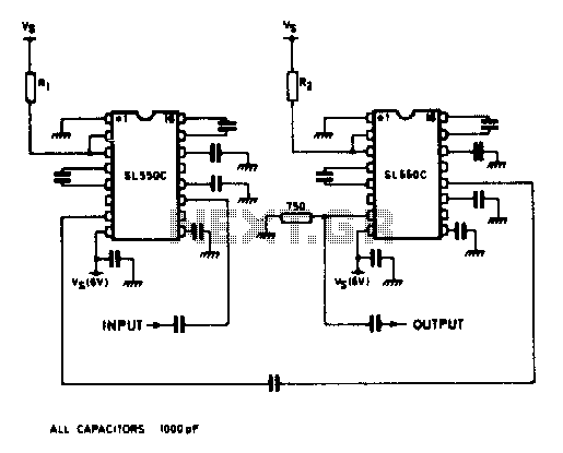
A wideband high gain configuration using two SL550s connected in series. The first stage is connected in a common emitter configuration, while the second stage is a common base circuit. Stable gains of up to 65 dB can be...
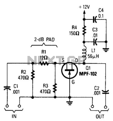
Using an MPF102 JFET, this circuit has a 50-ohm input impedance. The load impedance should be approximately 470 ohms. A 3:1 matching transformer can be utilized to return the impedance to 50 ohms. This circuit will exhibit a gain...
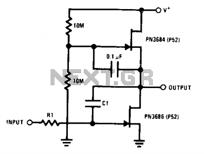
This circuit employs the "µ-amp" technique to achieve a very high voltage gain. By using a CI in the circuit as a Miller integrator or capacitance multiplier, this simple configuration can manage very long time constants. The described circuit primarily...
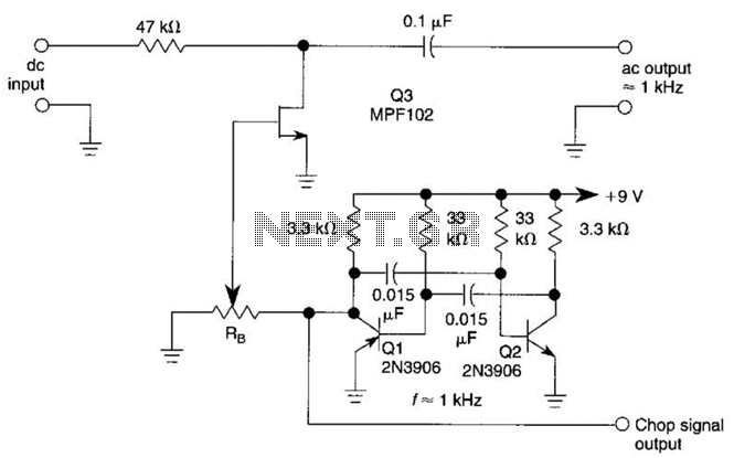
A JFET (MPF102) is utilized to chop a DC signal for amplification in an AC-coupled amplifier. Q3 serves as the chopper element, while Q1 and Q2 create a multivibrator to generate the chopping signal. Additionally, resistor Rr establishes the...
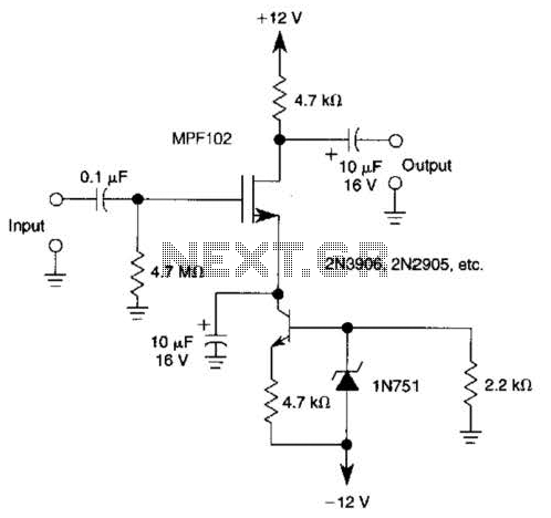
A current source (MPF102) in the source lead of the bipolar transistor 2N3906 allows for precise control of drain current. The circuit incorporates an MPF102 JFET configured as a current source, which is connected to the source terminal of a...
A JFET-bipolar cascode circuit is designed to deliver complete video output for driving the cathode of a CRT. The configuration offers an approximate gain of 90. The cascode arrangement mitigates issues related to the Miller capacitance of the JFET...