
Hobby-Servo Encoder Retrofit
The encoder strip installation process involves several critical steps to ensure proper functionality and durability. The choice of label material is essential; laser-printed sticky labels are preferred due to their adhesive properties and resistance to wear. The use of Avery "WeatherProof White Labels" #15510 is suggested for their reliability and ease of use. When cutting the labels, a slight excess at both ends facilitates a secure wrap around the gear barrel, which is vital for maintaining alignment during operation.
Preparation of the gear barrel is crucial for optimal adhesion. The surface must be thoroughly cleaned to remove any grease or contaminants that could hinder the label's stickiness. Roughening the barrel with an emery board creates a textured surface that increases the bond between the label and the gear. After cleaning and preparing the surface, the label can be applied. Care should be taken to align the label correctly to avoid misalignment, which could cause operational issues.
Once the label is in place, it is recommended to burnish the surface to ensure full contact and adhesion. The application of super glue at the overlapping edges can provide additional security, though it should be done cautiously to avoid excess that could affect the gear's operation. After the label is affixed, the gear train should be reassembled carefully, ensuring that the newly applied encoder strip does not interfere with the gear's movement.
The modification of the motor casing to include a notch is a necessary step to allow for the encoder strip's visibility and functionality. The dimensions of the notch must be adhered to precisely to avoid compromising the structural integrity of the casing. After the notch is created, the circuit board should be positioned correctly, with the sensor aligned with the encoder strip for accurate readings.
Finally, the integration of this encoder setup with an ATMEGA128 Mica2 mote card allows for advanced tracking of motor performance. The software developed for this system is capable of monitoring both pulse-width and pulse count, providing valuable data regarding motor speed and distance traveled. This comprehensive approach ensures that the encoder system is both effective and reliable in its application.The encoder strip should be laser-printed on sticky label material (ink-jet might work, I haven`t tried it). It is then cut out and wrapped around the barrel of the second drive gear. I used bright white sticky address labels Avery "WeatherProof White Labels" #15510 from my fiendish local Office Depot.
The measurements shown on the drawing are to fit the second gear of the motor. I cut them slightly longer than the length at both ends so there is a bit of overlap when wrapped around the gear barrel. Here is a 300dpi image of a set of them with cutlines, perhaps positioned to print correctly on the 1x2-5/8" labels specified above: StripePrint.
They have a bit of leader on each end to make a good overlap. Clean all the grease off the gear with rubbing alcohol or brake cleaner or something even worse. Then rough-up the gear barrel surface with an emery board or small file so the label will have something to stick to. Then clean everything again and don`t touch the barrel surface. Wrap the cut label strip, starting with the white block, around the barrel. Be careful to keep it aligned with the gear so it goes on straight with no crinkles of bubbles. The last black block should overlap the starting edge just slightly. Then carefully burnish the label down with a piece of smooth hard plastic. (. I just happen to have an old press-type burnishing tool for the job, that shows my age I guess. ). I also put a small drop of super-glue on the joined edges in the hope that this will hold them together, I have no idea, yet, how long these labels will stick to the un-sticky nylon gear.
Put the gear train back together the way it was and make sure there is clearance for the stripe as it rotates. During reassembly you can also put a little lube on the gears and bearings (you can get the expensive stuff from junun, or go to an auto parts store and get some SilGlide or other silicon lube).
But be sparing so it doesn`t get all over the stripe after the motor has run for a while. Cut out a notch in the appropriate side of the motor casinglid. The notch should be about 4. 7mm(. 185") deep and 10mm(. 400") wide starting at the inside edge of the bolt hole as shown (or 14. 6mm(. 575") from the outside of the lid). Use a jewler`s or other fine toothed saw, just clipping the box with your diagonal cutters will crack the plastic. Once the sides are cut you can use a knife or scribe to score the bottom and break it out with pliers.
File or otherwise deburr the sharp edges. As far as I can tell Goop (extra sticky silly-seal) is the only thing that works on everything involved. So put a tiny glob of it on the lid where the circuit card will go and stick the board firmly in the cutout corner of the lid.
Note that the sensor should be directly across from thebearing hole of the newly encoder-strip-ized gear. Fold the wires back as far as they can go and clamp the board down with a paper clip until the Goop sets.
Make sure it is seated into the corner of the lid before it sets up. Once everything is set you can reassemble the motor lid and see if the gear cuts up the wires or it makes awful noises. After it`s all over I try to re-seal the hole in the case with a layer of electrical tape on either side of the cable to the motor.
This might work. Or not. You`re on your own here unfortunately. I use these with an ATMEGA128 Mica2 mote card from Xbow. com and my software is written for the TinyOS "operating system" that runs on these cards. If that`s your thing, then get this ZIP1. An updated version benefitting from the "Calculus Addenda" below is here: ZIP2. You want to keep track of both the pulse-width and the number of pulses you get. The pulse-width (period between rising edges, in, say, milli-sec) is directly related to the speed of the motor; a longer period is a slower speed, and v-versa. The number of pulses is directly related to the distance traveled; as stated before there are 44 pulses p
🔗 External reference
Related Circuits
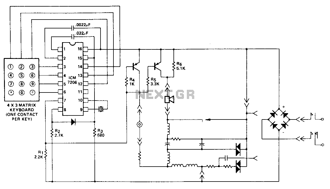
This encoder utilizes a single contact per key keyboard and implements all other switching functions electronically. A diode is positioned between terminals 8 and 15 to prevent the output from exceeding 1 volt negative in relation to the negative...
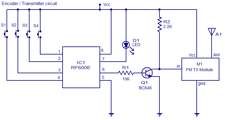
The circuit diagram illustrates an FM remote encoder/decoder utilizing the RF600E and RF600D integrated circuits (ICs). These components are engineered to deliver a high level of security and operate within a voltage range of 2 to 6.6V DC. Applications...
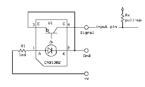
The receiver chip uses a Panasonic 4602 38KHz receiver and that's it for external components. It has the serial input (GP3), two RC hobby servo outputs (GP0/GP1), and three digital outputs (GP2,4,5). Here is the code for the receiver...
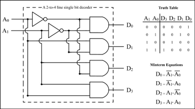
The Encoder and Decoder are different types of combinational circuits used to convert binary information to decimal, octal, and hexadecimal formats, and vice versa. A decoder is a combinational circuit that converts n-bit binary information into 2^n unique outputs....
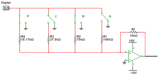
Encoders and decoders are circuits that convert analog signals to digital signals and digital signals to analog signals. The input is in digital form, while the output is a continuous sine wave or analog wave. Encoders and decoders play a...
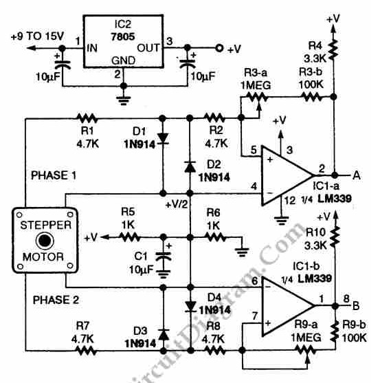
The circuit illustrated in the schematic diagram below allows for the visualization of the direction and shaft rotation of a stepper motor on an LED display. Instead of utilizing a digital rotation encoder as an input, this circuit employs...