
Hot Springs Reverb
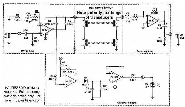
The circuit design for the Hot Springs system incorporates a reverb tank and a dedicated circuit board, which requires careful placement to minimize interference from ambient electromagnetic fields. This is crucial for maintaining signal integrity and ensuring optimal performance. The input and output jacks are mounted on a patch panel, allowing for easy integration with other effects devices.
To connect the Hot Springs to a mixing console, the effects or auxiliary send bus is utilized. The signal from the console is routed to the input of the Hot Springs, where it undergoes processing through the reverb tank. The processed signal is then returned to the mixer through one of its input channels, enabling the operator to control the reverb level within the overall mix.
For optimal signal routing, a Y cord or splitter is recommended. This configuration allows the instrument signal to be sent simultaneously to both channel one of the amplifier and the Hot Springs input. The output from the Hot Springs is then routed to channel two of the amplifier. This setup permits independent control of the reverb effect through the volume control of channel two, allowing for precise adjustments to the reverb level while maintaining the original instrument signal on channel one.
In summary, the Hot Springs system's design emphasizes ease of integration with existing audio equipment, allowing for versatile reverb effects management while ensuring minimal interference and optimal audio quality.The Hot Springs tanks and circuit board should be mounted in a location that is free of ambient electro-magnetic fields. The input and output jacks are typically placed on a patch panel with other effect`s inputs and outputs.
In use, the effects or aux send buss of the console patches to the Hot Springs input and the output of the Hot Springs returns to one of the mixer inputs for control of reverb level in the total mix.h Use a Y cord or splitter to send the instrument signal to both channel one of your amp and the Hot Springs input. Then patch the Hot Spring`s output to channel two of the amp. Adjust the amoung of reverb with channel two`s volume control and adj 🔗 External reference
Related Circuits
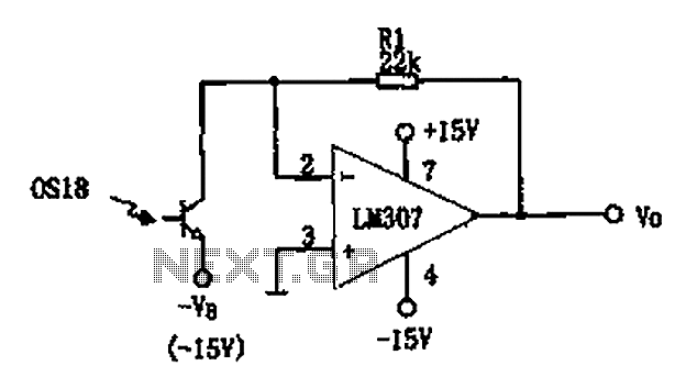
The circuit described is a photoelectric receiver amplifier designed to amplify the electrical signals generated by photodiodes or phototransistors in optoelectronic devices. When the intensity of incident light varies, the photosensitive device generates a corresponding voltage or current. The...
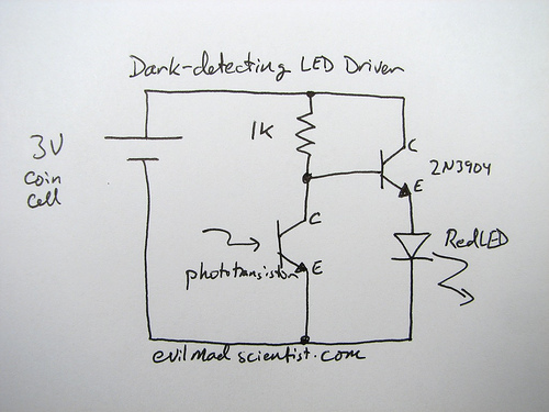
A circuit that uses a phototransistor to create a light-sensitive switch. When there is no light in the room, the LED connected to the phototransistor lights up, and when there is light, the LED turns off. Any schematic or...
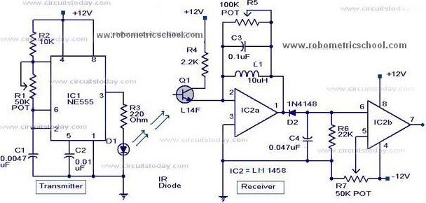
All components used in the Moving Sensor/Detector Schematic Diagram utilize the IC NE555 and the Phototransistor L14F. The primary component in this circuit is the IC NE555, along with an IR LED, the Phototransistor L14F, and the IC LM1458....

The circuit utilizes a tuned circuit for frequency selection, designed to operate at approximately 51 kHz. The 2N3565 transistor amplifies the output generated by the tuned circuit. The described circuit operates on the principle of resonance, where the tuned circuit...
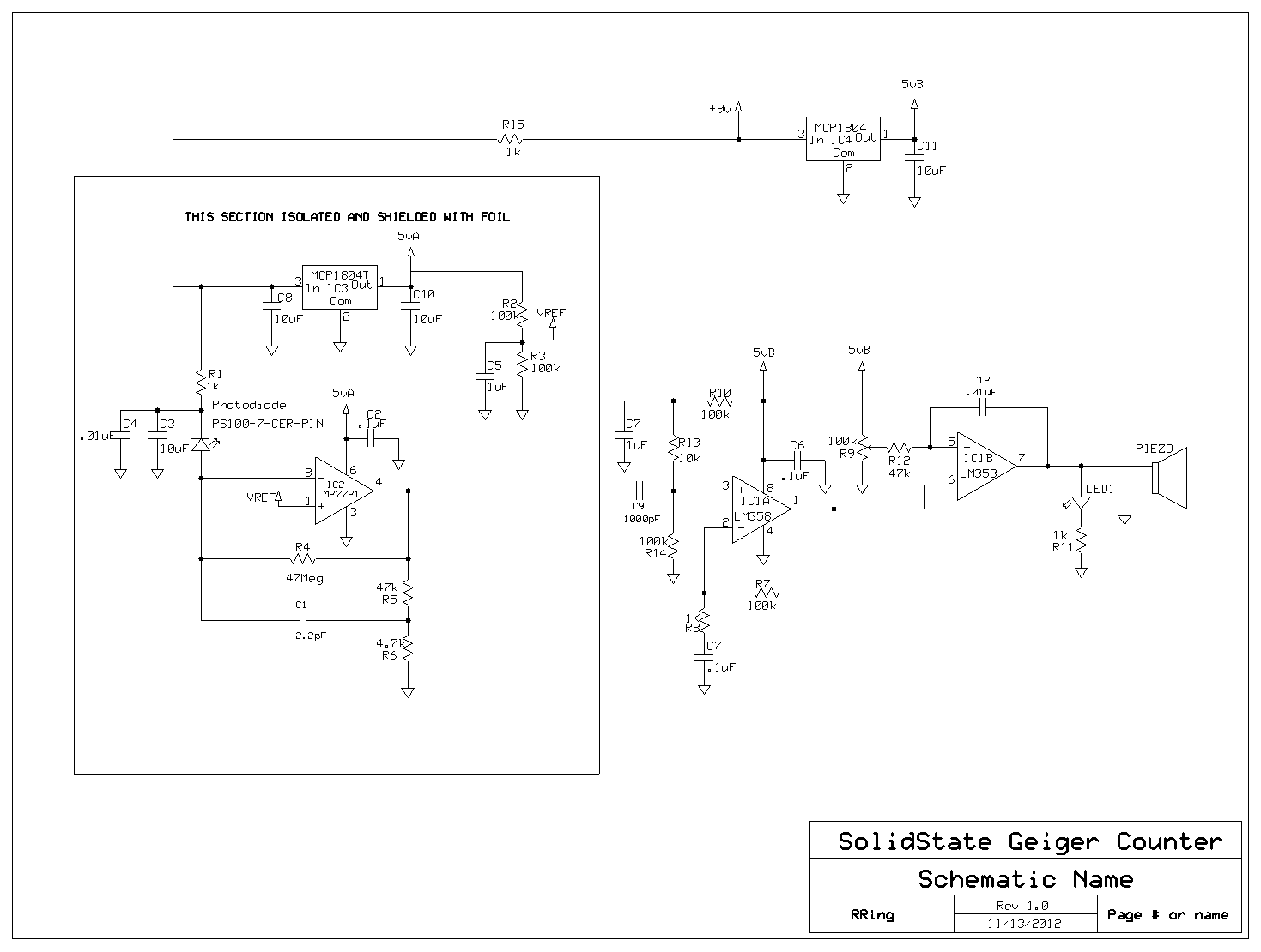
Photodiodes convert light into current, and this current can be converted into voltage and amplified. While this process seems straightforward, designing a photodiode detector for gamma photon detection is more complex. Although the circuit is not particularly complicated, the...
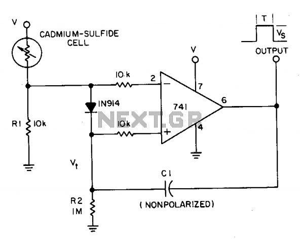
A photocell circuit provides automatic threshold adjustment. Monostable action prevents undesired retriggering of the output. With only one op amp IC, the circuit offers automatic adjustment of its trigger level to accommodate various light sources, changes in ambient light,...