
How to build a simple remote control system
The project involves the implementation of a radio frequency (RF) communication system utilizing Ming RF transmitter and receiver boards. The schematics have been updated to enhance clarity and detail, making it easier to identify the components and their connections. The RF transmitter operates by modulating a carrier frequency, which is then transmitted through a quarter-wave antenna. This type of antenna is chosen for its effectiveness in achieving a good balance between size and performance, providing an efficient radiation pattern.
The receiver is designed to demodulate the incoming RF signal, extracting the original information signal for further processing. The overall design emphasizes cost-effectiveness without compromising performance, making it suitable for hobbyists and educational purposes. The use of quarter-wave antennas contributes to extended operational range and improved signal quality, which is crucial for applications requiring reliable communication over distances.
Overall, the updated schematics reflect a comprehensive approach to RF design, incorporating best practices for component selection and circuit layout, ensuring that the system operates effectively in various conditions.Due to the huge interest in this project, I have just recently finished the NEW schematics. The older schematics were scanned and pretty poor quality. These new ones should make it considerably easier to recognize the parts used for the project. The Ming RF transmitter and receiver boards used for this project are relatively inexpensive and perform admirably considering the meager price. Using the quarter wave antennas, I have had some excellent results with operating distance as well as overall operation.
🔗 External reference
Related Circuits
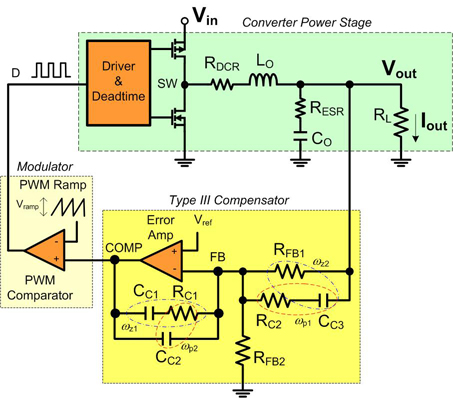
Before designing with one of today's powerful buck regulator ICs, it is essential to have a thorough understanding of voltage mode control and compensation. Voltage mode control is a widely used method in switching power supplies, particularly in buck converters....
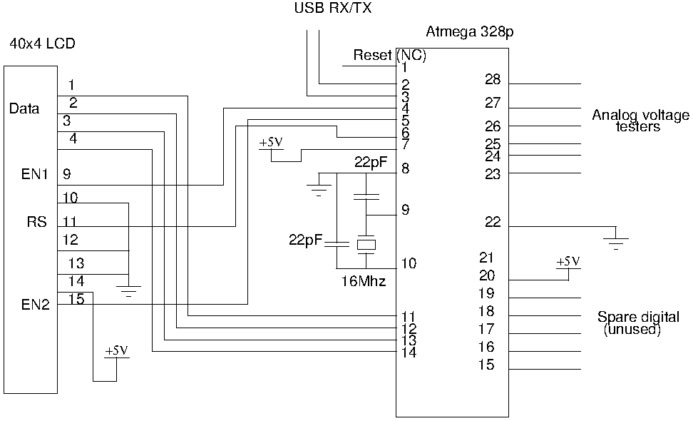
Drive a four-line LCD panel using an Arduino. The project initially aimed to control the LCD for displaying arbitrary information but evolved to include functionalities such as timekeeping, EEPROM read/write operations from the Atmel 328p, and voltage measurement. Multiple...
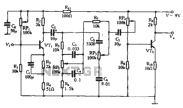
This article presents a diagram of an attenuated tone control circuit. The circuit primarily consists of transistors and RC networks as its components. The circuit operates in such a way that the shunt effect of capacitor C4 and resistor...
This circuit is designed for precise centigrade temperature measurement. It features a transmitter section that converts the sensor's output voltage, which is proportional to the measured temperature, into frequency. The output frequency bursts are transmitted through the mains supply...
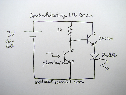
The following circuit illustrates a simple and inexpensive dark-detecting LED circuit. Features include the use of photoresistors, specifically a photocell or LDR, and an LED. This circuit utilizes a light-dependent resistor (LDR) as the primary sensing element. The LDR exhibits...
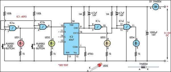
This circuit is a two-player game that combines strategy, speed, and physical agility. Each player has a row of four LEDs in front of them, with a push-button next to each LED. Pressing a button illuminates the corresponding LED....