
How to Troubleshoot a Gas Dryer with No Heat
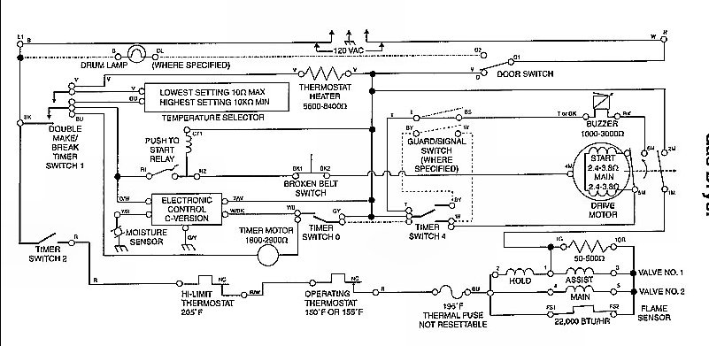
To troubleshoot the ignition system further, it is essential to understand the roles of the centrifugal switch and pressure switch in the operation of the burner assembly. The centrifugal switch, typically found in blower motors, is responsible for engaging or disengaging components based on the speed of the motor. When the motor reaches a specific RPM, the centrifugal switch closes, allowing power to flow to the ignition system. To test the centrifugal switch, it is necessary to ensure that the motor is functioning correctly and reaching its operational speed. A multimeter can be used to check continuity across the switch contacts when the motor is running. If there is no continuity, the switch may be faulty and require replacement.
The pressure switch, on the other hand, monitors the pressure levels within the combustion chamber or venting system. It is designed to ensure that the system is safe to operate by confirming that there is adequate airflow or pressure before allowing the ignition sequence to proceed. To test the pressure switch, a manometer can be used to measure the pressure at the switch’s input port while the system is operating. If the pressure is within the specified range but the switch does not close, it may be defective. Additionally, verifying the wiring and connections to the pressure switch is crucial, as loose or corroded connections can lead to operational failures.
In summary, a systematic approach involving the testing of both the centrifugal switch and pressure switch using appropriate tools will aid in diagnosing the root cause of the ignition failure. Ensuring that all safety switches and components are functioning correctly is vital for the safe operation of the system.No fire replaced ignitor still no fire checked for voltage to valve assy none checked safety switches on fire box & vent normally closed condition okayhow do I check the centrifical switch & pressure switch for proper operation.. 🔗 External reference
Related Circuits
This is a straightforward and easy-to-construct heat or temperature sensor alarm circuit. A notable feature of this circuit is its ability to emit a beep sound and flash an LED in response to temperature changes. The heat or temperature sensor...
The heating element is connected in series with two back-to-back 16 amp silicon-controlled rectifiers (SCRs), which are controlled by a small pulse transformer. This pulse transformer features three identical windings: two are dedicated to providing trigger pulses to the...
The Thermistor, or NTC (Negative Temperature Coefficient) of 10K, is a standard type. Most types will work. The one in the diagram is a 10K model made by Fenwal (#197-103LAG-A01). The resistance lowers as the surrounding temperature increases, which...

The initial step involves searching online for information. After some investigation, it was discovered that the QAA75 sensor is manufactured by Siemens. This expanded the search parameters. It was found that Siemens refers to the communication method as a...
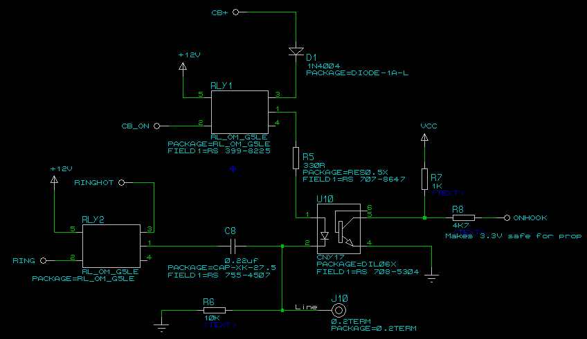
A four-channel DMX512 controlled ringer. The Mk 3 will also incorporate a ringing supply generator, making it reproducible by those without access to the BT ringing supply Number 7. The ringer is microprocessor-controlled, utilizing a Parallax Propeller-based chip, specifically...
The original coil that came with the Heathkit project was preassembled at the factory. It had a diameter of around 15 cm (6 inches). A larger (30 cm, 12 inches) coil can be made using the following data. The design...