
Humidity Sensor
Humidity measurement is critical in various applications, including meteorology, HVAC systems, agriculture, and food storage. The measurement is typically expressed in relative humidity (RH), which is the ratio of the current amount of water vapor in the air to the maximum amount of water vapor the air can hold at that specific temperature.
To create an electronic humidity sensor circuit, a common approach involves using a capacitive or resistive humidity sensor. Capacitive sensors operate by measuring changes in capacitance caused by the absorption of moisture in a hygroscopic material. In contrast, resistive sensors measure changes in resistance as humidity levels fluctuate.
A basic schematic for a capacitive humidity sensor circuit may include the following components:
1. **Humidity Sensor**: A capacitive sensor that changes its capacitance based on the surrounding humidity levels.
2. **Microcontroller**: A microcontroller such as an Arduino or PIC that reads the sensor output and processes the data.
3. **Analog-to-Digital Converter (ADC)**: If the microcontroller does not have a built-in ADC, an external ADC may be required to convert the analog signal from the humidity sensor into a digital signal for processing.
4. **Power Supply**: A stable power supply circuit to ensure the sensor and microcontroller operate within their specified voltage ranges.
5. **Display Module**: An optional LCD or LED display to visually present the humidity readings.
The circuit can be designed to include a feedback mechanism to adjust environmental conditions based on the measured humidity, such as activating dehumidifiers or humidifiers. Proper calibration of the sensor is essential for accurate readings, and regular maintenance may be necessary to ensure long-term reliability.
Overall, the design of a humidity measurement circuit requires careful consideration of the sensor type, the processing unit, and the interface for data output, ensuring that it meets the specific needs of the intended application.Introduction Humidity is the amount of water vapor in the air, expressed as a percentage of the maximum amount that the air could hold at the given temperature.. 🔗 External reference
Related Circuits
A rain sensor alarm circuit is a useful device for alerting when rainfall occurs. The rain detector circuit presented is straightforward, utilizing only three components while maintaining high sensitivity to detect rain or moisture. The sensor can be constructed...
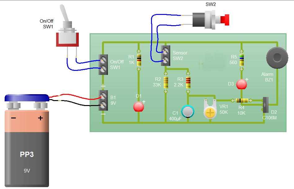
When the sensor switch SW2 is pressed, the LED D3 and the alarm are activated for a certain duration. The timing of the circuit is determined by the resistor R3 and capacitor C1. Additional details regarding the RC circuit...
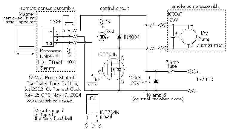
The 12 Volt power in my application comes from a small solar power system; it may also be provided by a suitable wall-wart DC power supply. The cistern is located below the toilet tank; the pump moves the water...
Capacitive touch sensors operate based on the electrical capacitance associated with the human body. When a finger approaches the sensor, it establishes a capacitance to the ground, typically ranging from 30 to 100 pF. This phenomenon can be utilized...
a more complex detector circuit which turns the relay on for an adjustable period of time. When the beam is broken, the LED goes on, your effect is powered, and capacitor C1 begins charging. As C1 is charging, the...
For several years, a rear fog lamp has been mandatory for trailers and caravans to enhance visibility in foggy conditions. When the fog lamp is activated, the fog lamp of the towing vehicle must be turned off to prevent...