
IGNITION TIMING LIGHT
The direct-trigger timing light circuit operates by capturing the ignition pulse from the vehicle's ignition system, which is essential for timing adjustments in automotive applications. The connection to the spark plug allows the timing light to sense the precise moment of ignition, providing real-time feedback for tuning purposes.
In the circuit design, T1 represents a transformer that steps up the voltage from the ignition pulse to a level suitable for triggering the subsequent components. C1 is a capacitor that helps in smoothing the voltage spikes generated during the ignition process, ensuring stable operation of the timing light. SCR1, or Silicon Controlled Rectifier, is used to control the flow of current in the circuit. It is triggered by the voltage from the transformer and allows the high-voltage pulse to pass through to the timing light.
In Figure B, the inductive pickup serves as an alternative method for sensing the ignition pulse. This component detects the magnetic field generated around the spark plug wire, eliminating the need for a direct connection to the spark plug itself. This method can enhance safety and reduce the risk of damaging the ignition system. The output from the inductive pickup is then fed into the triggering circuit, which processes the signal similarly to the direct connection method.
Overall, these circuits are crucial for automotive technicians who require accurate timing information to optimize engine performance. The design ensures reliability and precision in measuring ignition timing, which is vital for maintaining engine efficiency and performance.Figure A shows the circuit of a direct-trigger timing light. The trigger voltage is taken from the car`s ignition circuit by a direct connection to a spark plug. A circuit using an inductive pickup is shown in Fig. B. A trigger transformer is used to develop the high-voltage pulse for triggering. The triggering circuit consists of T1, C1, SCR1, inductive pic.. 🔗 External reference
Related Circuits
In this figure, S1 initiates the timing process, and once the timer is activated, toggling this switch will not impact the timing operation. S2 serves as the OFF switch located in the center; toggling this switch allows the timer...
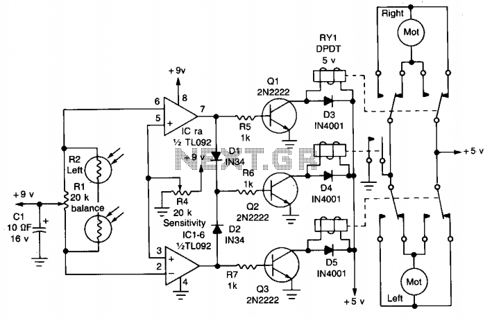
The circuit is designed to seek light, allowing a robot to follow a flashlight in a dark room. Two photocells are used to determine the direction of the robot's movement. Each photocell is connected to an operational amplifier configured...
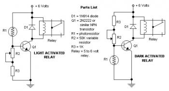
The potentiometer adjusts the trigger level. The diode in the circuit diagram is specified as 1N914, which is suitable for light-duty relays; however, since the 1N914 is a signal diode, it is not ideal. A 1N4001 or a better...
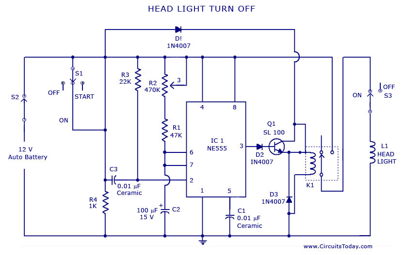
A circuit that can automatically turn off the headlights or lamps of a vehicle after a preset time. This light switching circuit is constructed using a 555 timer integrated circuit (IC). The described circuit utilizes the 555 timer IC in...
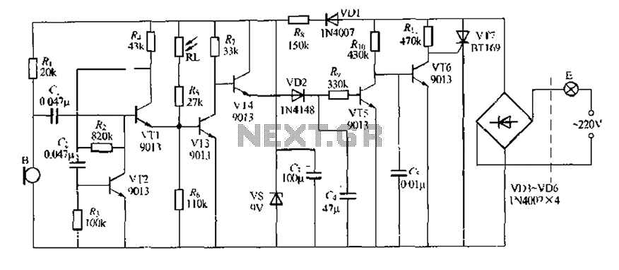
This circuit design is a sound and light control delay switch for staircase walkway lighting, featuring high voice sensitivity. In the evening, when someone walks on the stairs, their footsteps activate the electronic meter, turning on the lights. If...
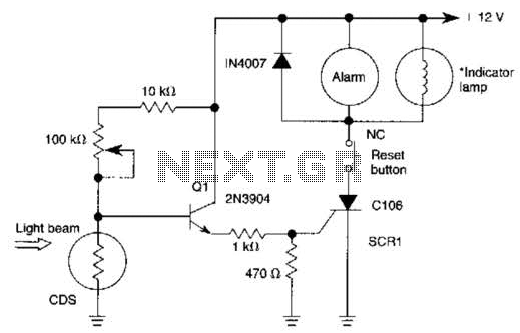
When the light beam that falls on the CDS photocell is interrupted, the transistor (EN3904) conducts, triggering SCR1 (CI06) and activating the alarm bell. SI resets the SCR. The alarm bell should be a self-interrupting electromechanical type. The lamp...