
Implementing the frequency counter
The connection between a Complex Programmable Logic Device (CPLD) board and a ChipKit board is essential for applications that require frequency measurement. The CPLD serves as a versatile logic component that can implement various digital functions, while the ChipKit board provides a microcontroller platform for executing higher-level tasks, including data processing and communication.
To establish this connection, it is crucial to identify the appropriate pins on both boards. The CPLD board typically has dedicated input pins that can be configured to read digital signals corresponding to the measured frequency. These input pins should be connected to the output pins of the ChipKit board, which may be configured to generate a square wave signal representing the frequency of interest.
The connection can be made using jumper wires or a ribbon cable, ensuring that the signal integrity is maintained. It is also advisable to include pull-up or pull-down resistors on the CPLD input pins to stabilize the signal levels and prevent floating inputs, which can lead to erroneous readings.
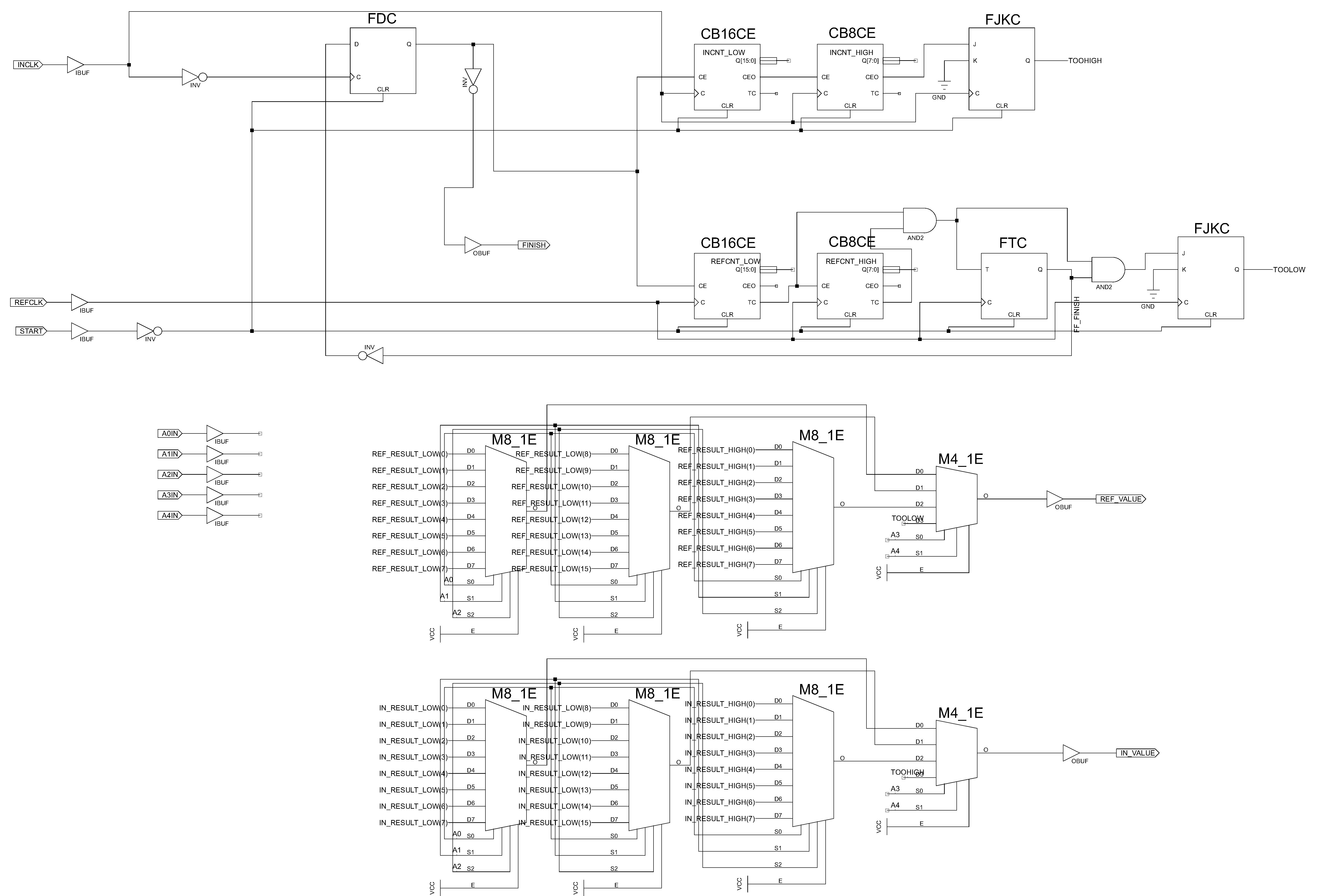
Once the physical connection is established, the CPLD must be programmed to interpret the incoming frequency signal. This typically involves writing a hardware description language (HDL) code that defines the behavior of the CPLD in terms of counting pulses or measuring the time period of the incoming signal. The ChipKit board, on the other hand, should be programmed to handle the data received from the CPLD, which may involve serial communication protocols such as UART or SPI for transmitting the frequency data to a host computer or other peripherals.
In summary, the integration of a CPLD board with a ChipKit board for frequency measurement involves careful planning of the connections, appropriate signal conditioning, and programming both devices to ensure accurate and reliable data acquisition.Connecting the CPLD board to a ChipKit board, to be able to read the measured frequency. 🔗 External reference
Related Circuits
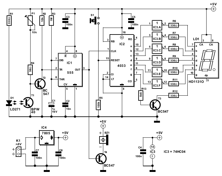
The circuit detailed here counts the number of times an infrared beam is interrupted. It can be utilized to track the number of individuals entering a room or to monitor how frequently an object, such as a ball, passes...
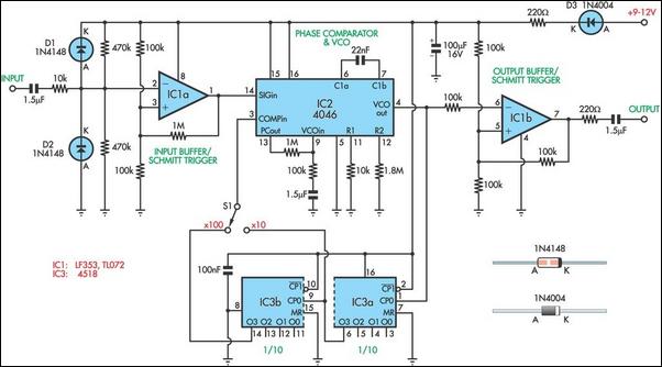
When designing bass reflex loudspeaker cabinets, it is essential to measure the speaker's resonance with an accuracy of approximately 1%. This requires an audio oscillator and a frequency counter. However, the accuracy and resolution of a frequency counter when...
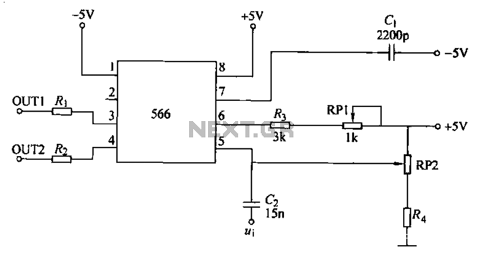
A frequency modulator utilizing the NE566 integrated voltage-controlled oscillator is depicted in the provided figure. When the DC potential at the signal input terminal is fixed, a constant frequency oscillation cycle is established. By varying the input terminal potential,...
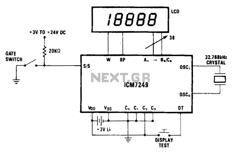
The display indicates each increment. In mode 2, external debouncing of the gate switch is unnecessary, provided that the switch bounce duration is less than 35 ms. The 3 V lithium battery can be replaced without interrupting operation if...
This circuit measures the distance covered during a walk. Hardware is located in a small box slipped in pants pocket and the display is conceived in the following manner: the leftmost display D2 (the most significant digit) shows 0...
This voltage-to-frequency converter circuit features a voltage-controlled oscillator with a deviation of 0.5%. The integrated circuit IC1 functions as a multivibrator, generating rectangular impulses of equal width. The output frequency is adjustable via the U1 voltage. The D3 diode...