
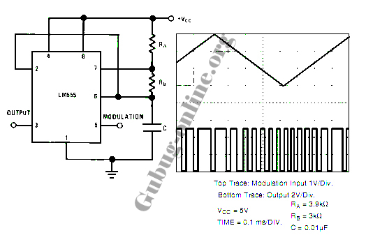
NE566 frequency modulator
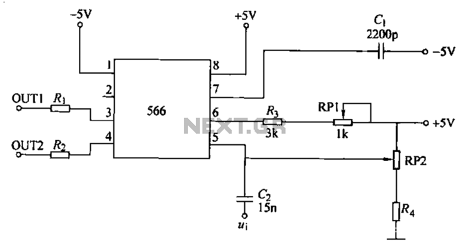
The NE566 integrated circuit operates as a voltage-controlled oscillator (VCO), allowing for frequency modulation based on the input voltage. The configuration presented enables the generation of a frequency-modulated signal, where the output frequency is directly influenced by the input voltage levels.
In this circuit, Ri and R2 serve as the timing resistors that help determine the oscillation frequency. The resistor Rd is connected to the timing capacitor, which influences the charge and discharge cycles, further affecting the output frequency. The variable resistor, RP2, plays a crucial role in fine-tuning the output frequency and can be adjusted to achieve the desired modulation characteristics.
When the input terminal potential is altered, the NE566 responds by adjusting the oscillation frequency, which is a fundamental aspect of frequency modulation. This allows the circuit to be used in various applications, including communication systems where the frequency of the transmitted signal must be modulated in response to the input signal variations.
The output frequency can be monitored and measured using an oscilloscope or frequency counter to ensure it aligns with the expected modulation range. The design can be expanded with additional components, such as filters or amplifiers, to enhance performance and signal integrity, depending on the specific application requirements. Overall, the NE566 frequency modulator is a versatile component in electronic circuits, providing reliable frequency modulation capabilities.A frequency modulator configured NE566 integrated voltage-controlled oscillator shown in FIG. When the signal input terminal potential DC position, forming a cycle of constant frequency oscillation; change input terminal potential, IC output frequency of the frequency modulation circuit changes accordingly. FIG component parameter reference value, when the resistance: Ri - R2 - lOOfl. Rd - lOkZRP2 - when 50kfl, 20 to the output frequency can be about a corresponding change in 40kHz; RP2 or change the value of G, the output frequency changes accordingly.
Related Circuits
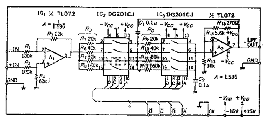
The circuit primarily consists of two Butterworth filters, designed to create a feedback amplifier with a gain of approximately 0.707. It features a differential input amplifier, where one input is grounded, resulting in a single input terminal. The attenuation...
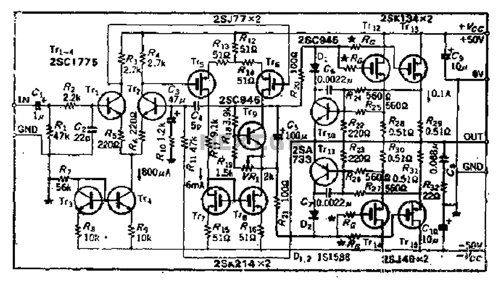
The circuit consists of three identical basic stages, with the second stage featuring a differential output from the power MOSFET, 2SJ77. A current mirror circuit utilizing 2SK214 is implemented. The operating current is 6mA; however, due to the power...
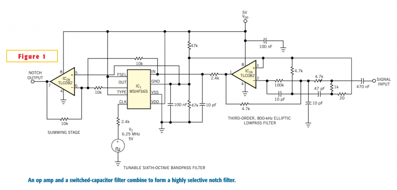
Although you can obtain universal, resistor-programmable switched-capacitor filters that are configurable as notch filters, most cannot operate at bandwidths higher than 100 kHz. Further, the typically 16- to 20-pin packages do not include a continuous-time, antialiasing filter to prevent...
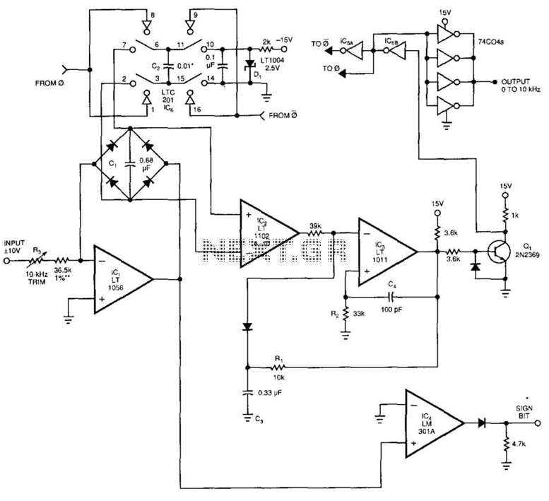
This voltage-to-frequency converter (VFC) accepts bipolar AC inputs. For -10 to +10 V inputs, the converter produces a proportional 0 to 10 kHz output. Linearity is 0.04%, and the temperature coefficient (TC) is approximately 50 ppm/°C. To understand the...
This design circuit for a pulse position modulator can be easily constructed using a 555 integrated circuit (IC). The pulse position modulator modulates the on-period while maintaining a fixed off-period. The circuit utilizes the 555 timer IC in astable mode...
AM radio receivers demodulate amplitude-modulated (AM) signals. The primary source of these signals is the Standard AM Radio Broadcast Band, although shortwave stations also utilize AM modulation. Amplitude modulation was developed between 1900 and 1917 by amateur radio enthusiasts....