
Improved non-inverting integrator
The modified circuit configuration presents a non-inverting integrator that eliminates the generation of the unwanted proportional term altogether, thereby negating the need for subtraction. In this design, ICla acts as a pre-inverter, processing the input signal before it reaches IClb. This pre-inversion ensures that the integrator operates solely on the integral component of the input signal, thereby enhancing the accuracy and performance of the circuit.
The implementation of this design not only simplifies the overall circuit but also improves the reliability of the output waveform. By removing the proportional term from the equation, the integrator can maintain a consistent response to varying input signals without introducing distortion or unwanted artifacts. The resulting output is a clean, smooth waveform that accurately reflects the integral of the input signal, making this configuration particularly advantageous in applications where precision is critical.
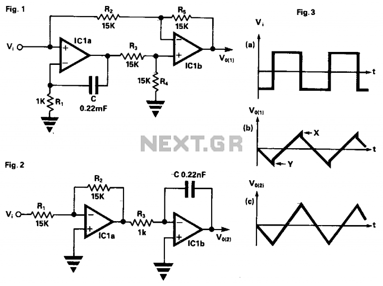
In summary, the transition from a standard integrator configuration to a non-inverting integrator through the use of ICla and IClb demonstrates a significant improvement in performance by addressing the issues associated with unwanted proportional terms. This refined approach highlights the importance of circuit design optimization in achieving high-fidelity electronic signal processing.In the circuit in Fig. 1, ICla produces the integral term required but also has the side effect of producing a proportional term not required, so this term is subtracted by IClb leaving a pure integral. If the ratio R2/R5 does not exactly match the ratio of R3/R4, the subtraction will not be complete and a small amount of the proportional term will reach the output.
The result of this with a square wave input is shown in Fig. 3a as small steps in the output waveform at points X and Y. This effect can be completely removed by using the simplified circuit shown in Fig. 2. Here the signal is pre-inverted by ICla, then fed to a standard inverting integrator IClb. The result is a non-inverting integrator with the advantage that the unwanted proportional term is never produced, so it does not need to be subtracted. 🔗 External reference
Related Circuits
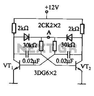
Figure 1 illustrates an enhanced trigger timing circuit that utilizes two Programmable Unijunction Transistors (PUTs). When a set signal is applied, the circuit is activated, causing transistor VT1 to enter the conduction state and energizing relay K. This action...
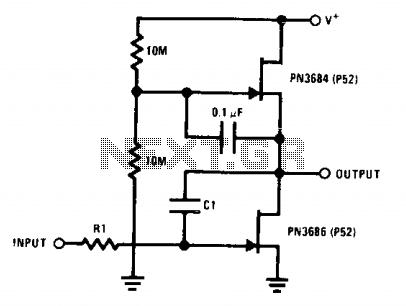
This circuit employs the "µ-amp" technique to achieve a very high voltage gain. By using a CI in the circuit as a Miller integrator or capacitance multiplier, this simple configuration can manage very long time constants. The described circuit primarily...
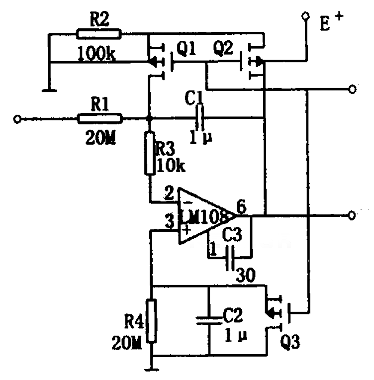
The integrator drift is minimal, not exceeding 500 V/s within the temperature range of -55°C to +125°C, as illustrated in the figure. The basic integrator is comprised of an operational amplifier, resistor R1, and capacitor C1. To enhance the...
This circuit is similar to the previous one but employs positive feedback to enhance the amplitude delivered to the speaker. It was adapted from a small five-transistor radio that utilizes a 25-ohm speaker. In the prior circuit, the load...
The circuit illustrated in Figure (A) consists of resistors R1 and R2 with values ranging from 15 to 18 kΩ, and capacitors C1 and C2 with capacitance values between 0.01 µF and 10 µF. Figure (B) depicts the oscillation...
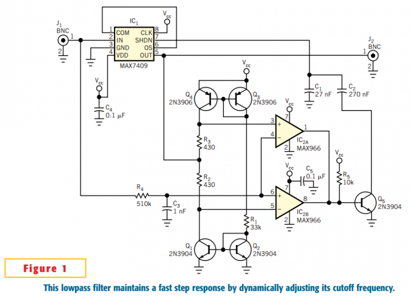
The circuit in Figure 1 accommodates lower cutoff frequencies without sacrificing the step-response time. A window comparator monitors the delta (difference) between the filter's input and output. When the delta exceeds ±50 mV, the filter increases its slew rate...
Warning: include(partials/cookie-banner.php): Failed to open stream: Permission denied in /var/www/html/nextgr/view-circuit.php on line 713
Warning: include(): Failed opening 'partials/cookie-banner.php' for inclusion (include_path='.:/usr/share/php') in /var/www/html/nextgr/view-circuit.php on line 713