
Increasing Regulator Current
The circuit described utilizes a 78xx series voltage regulator, specifically the 7812, which provides a stable output voltage of 12V. The 78xx series is well-known for its ease of use and reliability in various electronic applications. However, its current output is limited, typically to around 1A, depending on the specific model used.
To enhance the current capacity of the circuit, a power transistor is integrated into the design. This transistor acts as a current booster, allowing the system to supply higher current levels to the load without compromising the stability of the output voltage. The configuration typically involves connecting the transistor's collector to the output of the voltage regulator and the emitter to the load. The base of the transistor is connected to the output of the regulator through a resistor, which controls the base current and, consequently, the collector current.
When the load demands a current greater than 650mA, the voltage regulator alone cannot meet this requirement. At this point, the power transistor begins to conduct, supplying the additional current needed by the load. This mechanism ensures that the output voltage remains constant at 12V, even under varying load conditions.
Thermal management is crucial in this design. Since the power transistor can dissipate significant heat during operation, it is imperative to attach it to an adequate heat sink. This will prevent thermal overload and ensure reliable operation over extended periods. The heat sink should be selected based on the power dissipation characteristics of the transistor, which can be calculated using the formula: Power Dissipation (Pd) = (Vce * Ic), where Vce is the voltage drop across the transistor and Ic is the collector current.
In summary, the combination of the 7812 voltage regulator and a power transistor allows for increased current output while maintaining voltage stability. This configuration is suitable for applications that require reliable power delivery beyond the standard limits of the voltage regulator alone. Proper thermal management through the use of a heat sink is essential for the longevity and performance of the circuit.Although the 78xx series of voltage regulators are available with different current outputs, you can boost the available current output with this circuit. A power transistor is used to supply extra current to the load the regulator, maintaining a constant voltage.
Currents up to 650mA will flow through the regulator, above this value and the power transistor will start to conduct, supplying the extra current to the load. This should be on an adequate heat sink as it is likely to get rather hot. Suppose you use a 12v regulator, 7812. 🔗 External reference
Related Circuits
A current loop transmitter refers to a sensor system utilized in industrial 4-20mA current loop technology. This transmitter contains the... A current loop transmitter is a critical component in industrial automation and control systems, particularly in applications where analog signal...
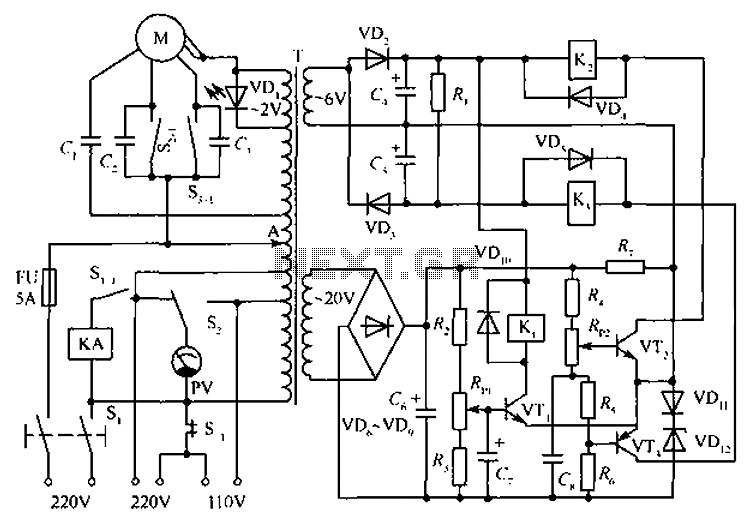
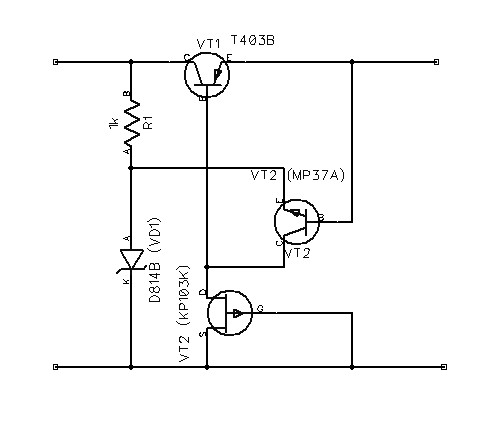
The circuit depicted in the figure includes an automatic voltage regulator (T) that maintains a constant output by utilizing a servo motor. The circuit features transistors VT1 and VT2 (3DK9), with a capacitance range of C (65 ~ 85)....
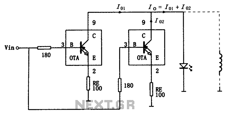
The high-speed parallel current drive circuit utilizes the OPA660 operational transconductance amplifier (OTA). An input signal, Vin, is connected to a 180-ohm resistor equivalent device at the base (pin 3) of the OPA660. The collector (pin 8) is directly...
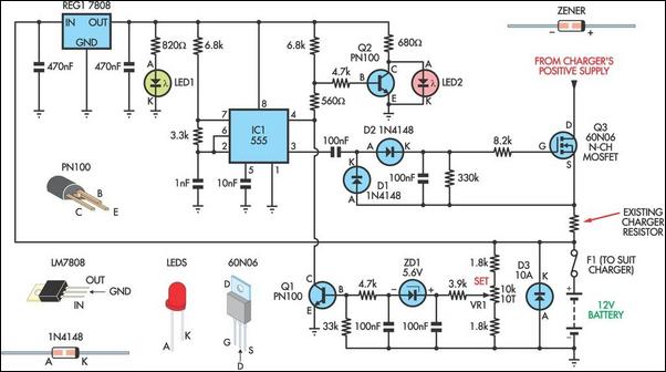
Most commercially available car battery chargers should not be connected to the battery for extended periods, as this can lead to overcharging and subsequent battery damage. This add-on circuit is connected in series with the battery being charged and...
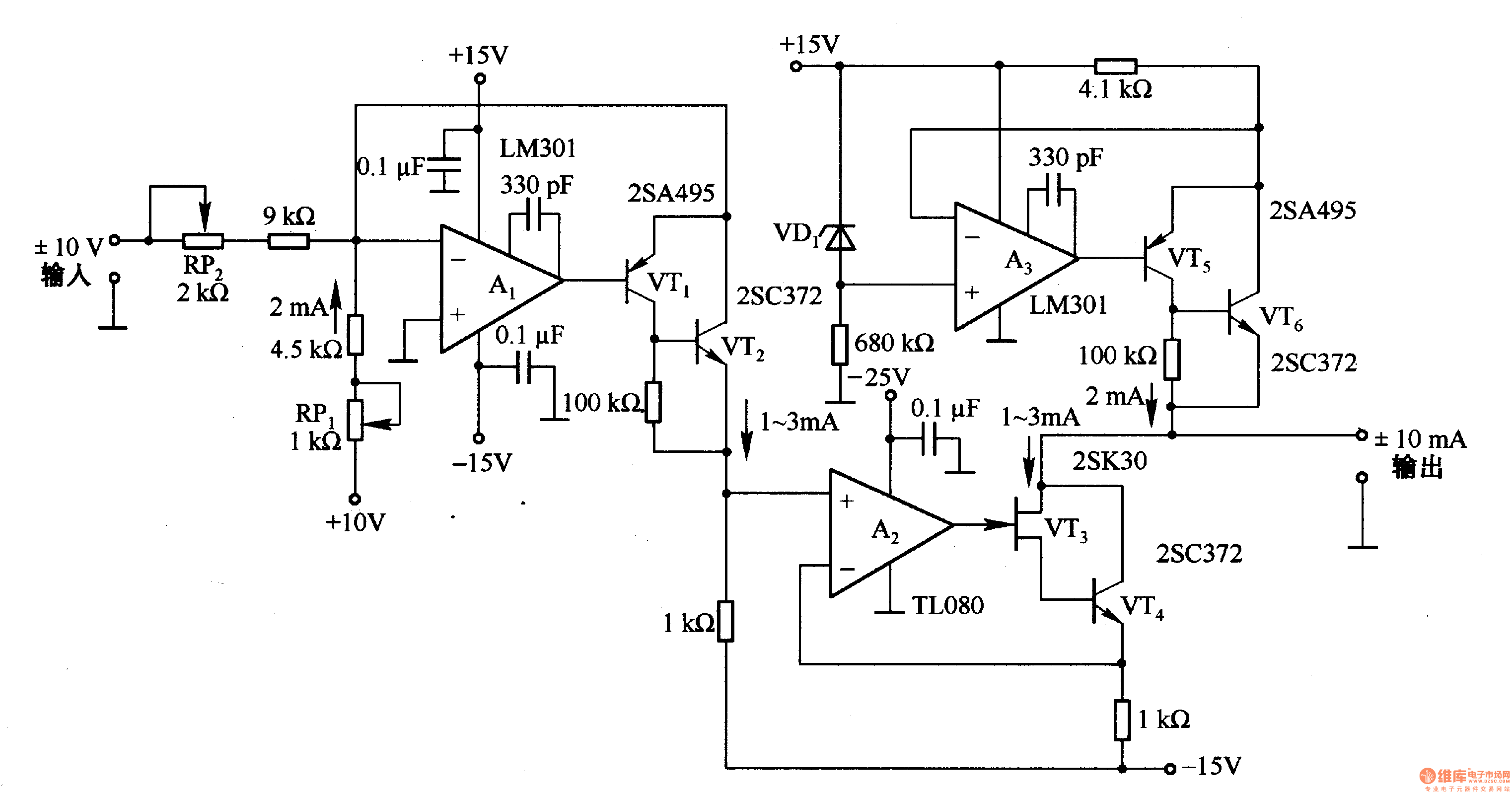
This circuit is designed for voltage-to-current conversion, specifically transforming a ±10V input voltage into a ±1mA output current. The conversion process is facilitated by operational amplifier A1 and transistors VT1 and VT2, which are responsible for altering the current...
The schematic diagram originates from a voltage regulator circuit utilizing a Field Effect Transistor (FET) power supply. This circuit features a feedback mechanism involving the FET VT3, which functions as a dynamic load for transistor VT2. This configuration enhances...