
interafce 16x2 lcd with avr
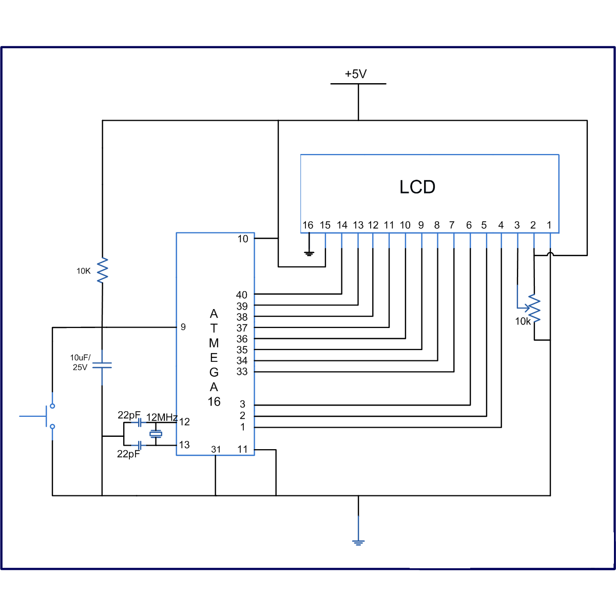
The interfacing of an ATmega16 microcontroller with a 16x2 LCD involves several key components and configurations that facilitate the display of characters. The 16x2 LCD consists of two rows, each capable of displaying 16 characters, and operates using a parallel communication protocol.
In this setup, the microcontroller communicates with the LCD in 8-bit mode, which allows for the transmission of data in 8-bit chunks. The data pins of the LCD are connected to Port A of the ATmega16, which is configured as an output port. This configuration enables the microcontroller to send character data directly to the LCD for display. The specific data pins are typically labeled D0 through D7, corresponding to the 8-bit data format.
Control signals are crucial for proper operation, and they are managed through Port B of the ATmega16. The control pins include:
- RS (Register Select): This pin determines whether the data being sent is command or character data. When RS is low, the microcontroller sends a command; when high, it sends data.
- R/W (Read/Write): This pin indicates the direction of data flow. When low, the microcontroller writes data to the LCD; when high, it reads data from the LCD.
- EN (Enable): This pin is used to latch the data into the LCD. A rising edge on this pin signals the LCD to read the data present on the data pins.
The initialization sequence of the LCD is critical for ensuring proper functionality. This typically involves configuring the LCD to operate in 8-bit mode, setting the number of display lines, and enabling the display. After initialization, the microcontroller can send characters to be displayed by writing to the appropriate data and control pins in a timed sequence.
In summary, the interfacing of an ATmega16 microcontroller with a 16x2 LCD in 8-bit mode involves connecting the data pins to Port A and the control pins to Port B, ensuring proper signal management for effective character display. This setup is fundamental in various applications, including embedded systems and user interfaces.LCD comes in various configurations and the most popular one is 16x2 matrix display. This article shows the interfacing of ATmega16 with LCD by displaying a simple character on the LCD. In this project LCD is working in 8-bit mode i. e. , the data transferred to the LCD must be in 8-bit data form. The PortA of ATmega16 is connected to data pins of LCD and is defined as LCD_DATA. PortB is defined as control pins (Rs, R/W and En). 🔗 External reference
Related Circuits
The module provides a pre-wired multiplex of a 4-digit common anode LED, which is quite useful. The soldering pad for these signals is shown in the first picture below. A friend provided an AT90S2313 chip, along with a simple...
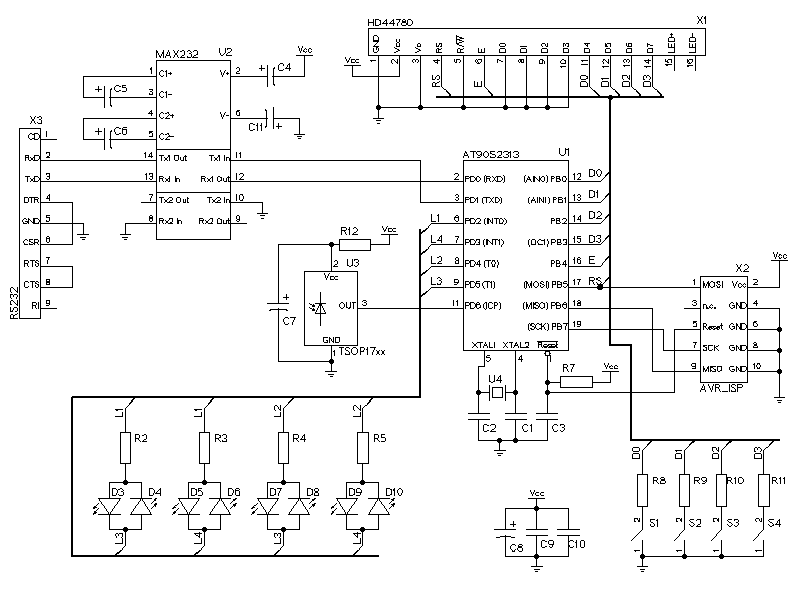
The LCD display is represented by the connector X1. It has a HD44780 compatible LCD controller and is using the 4-bit interface to send data to the LCD controller. The LEDs are multiplexed. It is possible to connect 12...
ISP programmer with circuit diagram for AVR Atmega32 microcontroller. This ISP burner circuit is an adaptation of the Pony programmer and uses PonyProg software. The ISP (In-System Programming) programmer designed for the AVR Atmega32 microcontroller facilitates the programming of the...
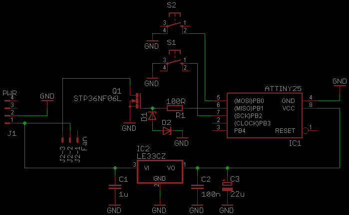
This document serves as a continuation of the previous work on PWM controllers utilizing 555 timers. The new design incorporates microcontrollers and MOSFETs in place of the 555 integrated circuits and transistors. Two versions have been developed: one equipped...
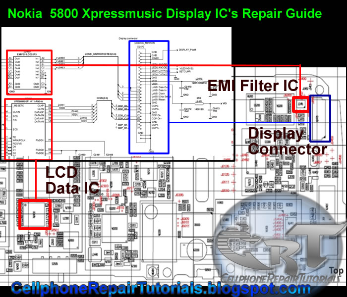
This mobile phone repair tutorial is applicable only if, after replacing a functional LCD or confirming that the LCD screen is operational, the display issue persists. If the LCD connector appears to be intact, a quick solution is to...
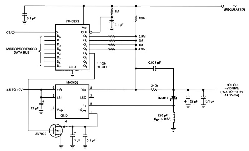
The following figure's switching regulator generates a negative voltage from the notebook battery supply. The microprocessor data bus drives a 4-bit DAC (74HC273), which can vary the regulator output between 6.5 to 11.5 V. This arrangement enables a staircase...