
sound activated lamp relay switch
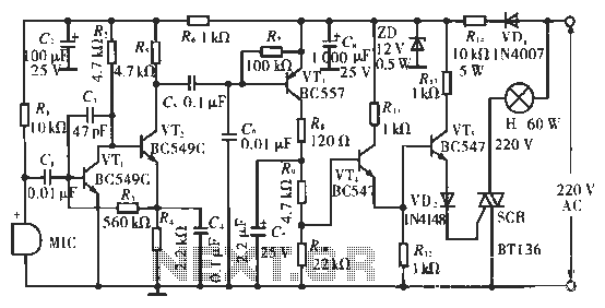
This sound-activated switch circuit is designed to respond to audio signals, providing an effective solution for various sound-controlled applications. The core component of this circuit is the transistor Q1, which serves as an amplifier for the audio input received from the microphone. The microphone captures sound waves, converting them into an electrical signal, which is then amplified by Q1. This amplification is critical, as it allows the circuit to respond to relatively low sound levels.
The resistor R1 plays a crucial role in determining the sensitivity of the circuit. By adjusting R1, the user can set the threshold level for the audio signal that will trigger the subsequent components. When the amplified audio signal exceeds approximately 0.7 volts, it activates the silicon-controlled rectifier (SCR). The SCR is a semiconductor device that allows current to flow in one direction when triggered, effectively acting as a switch.
The load connected to the output of the SCR can vary depending on the application. In the described configuration, lamp I1 serves as a visual indicator, lighting up in response to sound. However, by replacing lamp I1 with a relay, the circuit can control higher power devices. This relay can handle larger currents and voltages, enabling the activation of high-wattage lamps or other electrical appliances that require more power than the original lamp.
In summary, this circuit demonstrates a practical application of sound detection and amplification, providing a versatile solution for creating sound-activated devices. The ability to adjust sensitivity and control larger loads makes it suitable for various consumer electronics and automation projects.This simple circuit shown int the schematic diagram actives the switch using sound. We can use this circuit for various applications, such as automatic (sound-controlled) disco light or car`s LED light show. The Q1 amplify the audio from mic. The R1 is used to adjust the peak of signal to greater than about 0. 7 volts, act as sensitivity adjuster. A certain level, the signal coming from microphone, after amplification by Q1, will trigger the SCR and light lamp I1. If we change the lamp with a relay, then we can get a sound-activated relay/switch, which can be used to control more powerful / high wattage high voltage lamps.
🔗 External reference
Related Circuits
The following touch switch circuit utilizes a CA3240 dual BiMOS operational amplifier to detect small currents flowing between the contact points on a touch plate. The touch switch circuit employs a CA3240 dual BiMOS op-amp, which is known for...
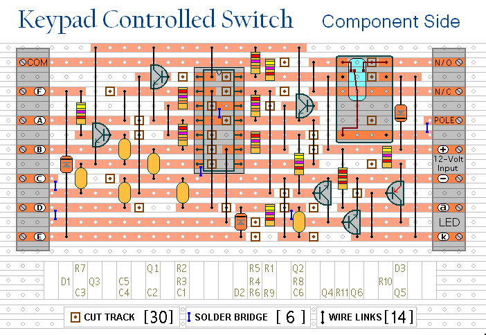
This is a universal version of the four-digit alarm control keypad. The design has been modified to free up the relay contacts, enabling the circuit to function as a general-purpose switch. A single pole changeover (SPCO) or single pole...
A low power, low cost DC lamp dimmer for a two-wire portable flashlight can be implemented with minimal or no heatsinking requirements. A single potentiometer, R3, is utilized to adjust the brightness of the lamp. Battery power is stored...
The circuit utilizes condenser microphones to detect sound and convert it into signal variations. This signal is then processed through directly coupled transistors VT1 and VT2, which form an amplification stage before being fed into a switching circuit. The...
This relay circuit is controlled by nearly any type of infrared remote controller. The circuit operates under the assumption that most remote controllers utilize high-frequency signals. The relay circuit described functions by receiving signals from an infrared (IR) remote control,...
This report deals with the design for a small asynchronous serial data switch. The switch architecture allows 14 serial ports supporting a subset of the RS-232 protocol. The requirements for the switch are discussed. The hardware interfaces are described...
Warning: include(partials/cookie-banner.php): Failed to open stream: Permission denied in /var/www/html/nextgr/view-circuit.php on line 713
Warning: include(): Failed opening 'partials/cookie-banner.php' for inclusion (include_path='.:/usr/share/php') in /var/www/html/nextgr/view-circuit.php on line 713