
jdm pic programmer

The circuit design provides a versatile platform for programming various PIC microcontrollers and other compatible devices. The use of the ICL7660 charge pump enables the generation of negative voltage, which is essential for ensuring proper data transmission and programming functionality. The careful selection of components, such as the 2N3906 and 2N2904 transistors, facilitates the necessary signal conditioning and voltage regulation required for reliable operation.
The programming adapter's layout should be meticulously planned on the Veroboard to accommodate the 25-way plug shell, ensuring that all connections are secure and that the circuit operates as intended. The indicator LED serves a critical role in providing visual feedback about the power status of the target board, which is vital for troubleshooting and ensuring that the circuit is powered correctly before programming attempts.
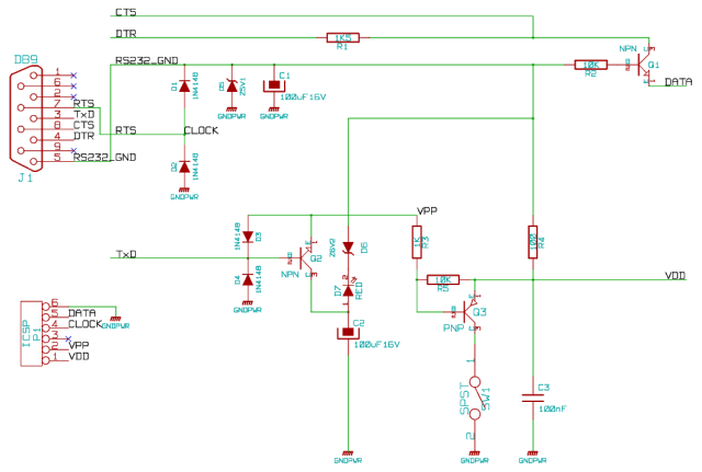
In summary, this circuit represents a robust and adaptable solution for in-circuit programming of PIC microcontrollers and related devices, with considerations for voltage levels, signal integrity, and user safety integrated into its design. Proper implementation of the described components and adherence to the power requirements will yield a functional and efficient programming tool.This is simple to build and uses ICProg or Vellemann`s K8076 picprog 2009 as the software. You need to add the serial device Driver for NT4, Win2K or XP. I don`t know about Vista/Win7 compatibility. It will run on Windows98 also. Any Linux software for JDM will work it such as or It`s aThis is simple to build and uses ICProg as the software. You need to add the serial device Driver for NT4, Win2K or XP. I don`t know about Vista/Win7 compatibility. It will run on Windows98 also. It`s an Incircuit programmer, though can be used with a simple adaptor for "bare chips". As well as 16F series PIC it can be used with a suitable connector for ISO smart cards and I2C devices such as 8 pin flash Memory. Select JDM on IC-Prog. It can be fitted in a 25 way plug shell on Veroboard U1 ICL7660 generates -5V from the target +5V to improve the output swing on the data (read from PIC to PC for verify) to PC which is fed by Q3 2N3906 (PNP) and Q5 2N2904 (NPN).
The ICL7660 charge pump clock drives voltage multiplier D8. D11. The output is thus +5V x 3 = 15V, but minus 4 x 0. 65V approx. , equals 12. 4v. The 12V programming voltage is switched by Q2 2N3906 (PNP) driven by PC TXD "break" signal via Q1 2N3904 (NPN). The diode D2 pulls LVM / PGM pin low in case this has not been disabled. D6 creates an approx. 4. 6V supply rail so that the protection diodes on PGD and PGC lines clamp the +12V via series resistors from RS232 at 5V rather than 5.
6V which could cause latchup. The Red LED indicates the Target board has +5V supply. Do not attempt to use Progamming adaptor without a regulated +5V supply on the target, or fitting a +5V jack and PSU connecting to the +5V and OV pins of programming adaptor that can power the entire target board. R1 & D7 converts the input data level for the PIC programming data from RS232, and R4 & D5 convert the RS232 level for the PIC programming clock.
Note that the programmer MUST have +5V supply from the target system. Pin connections for DH Microsystems ` Prototype board 🔗 External reference
Related Circuits
This circuit is capable of programming any Microchip processor ranging from 6 pins to 40 pins. The programmer is compatible with the PIC12, PIC16, PIC18, dsPIC24, and dsPIC30 families, utilizing an ICSP header which eliminates the need to remove...
This project is designed to program the 8-pin PIC12c508A and 18-pin PIC16F84 microcontroller chips to support the projects we have designed; however, it will also program a number of other 8-pin and 18-pin microcontrollers, and the full list can...

A fixed three-terminal integrated voltage regulator can be directly employed in various electronic devices as a voltage regulator. It features internal protections such as overcurrent protection, thermal protection, and safe operating area protection, making the circuit easy to use,...

A PIC16x84 processor can be utilized to generate a PSK31 or FSK31 signal. This signal may serve various purposes, including beacon transmissions, telemetry, experimentation, or QSOs, though the latter may involve some quirks. The PSK transmitter was initially designed...
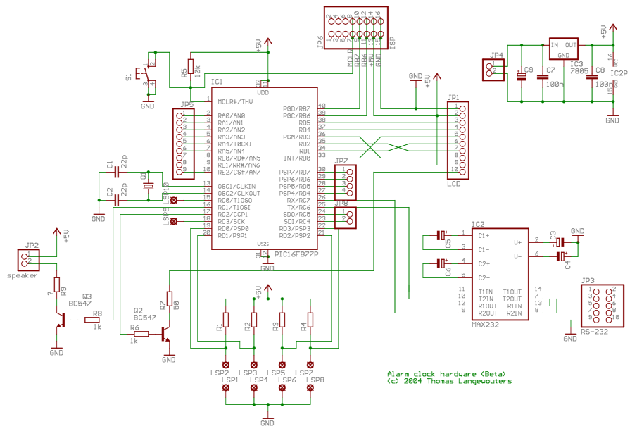
This project outlines a digital clock featuring an alarm function, utilizing a PIC16F877 microcontroller to achieve an accurate 1-second delay with Timer0 through Roman's zero error method. The time is displayed in large font on a 4G—20 character LCD,...
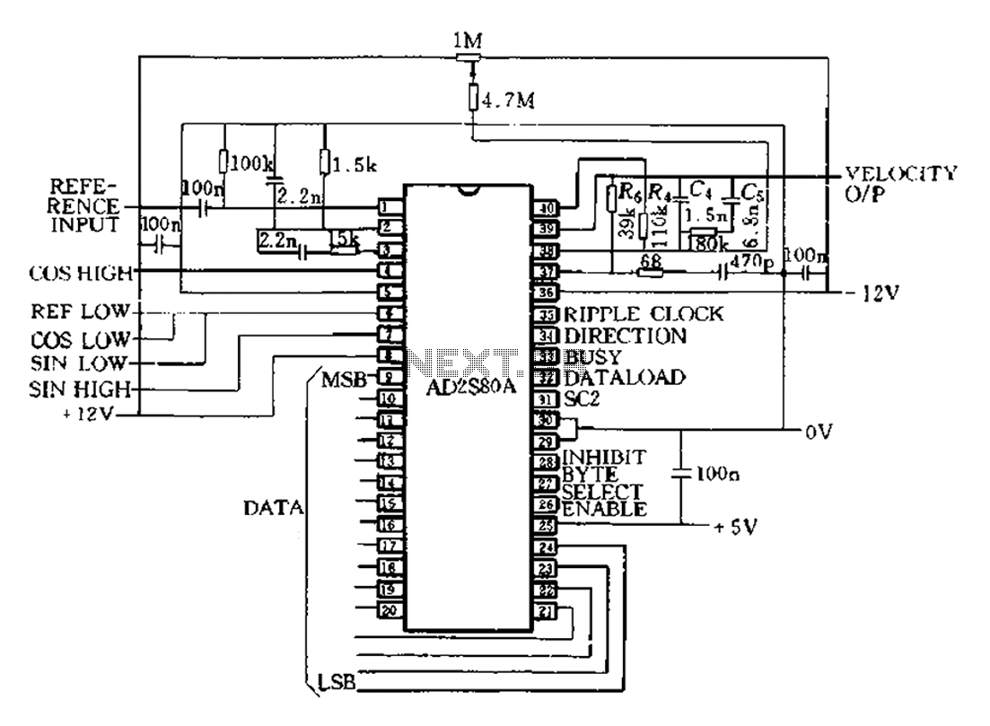
The AD2S80A represents a typical application circuit, detailing specific peripheral connectivity and device parameters. It is configured for a 12-bit resolution (SCl-0, Sc2 1) to select a reference frequency of 5 kHz. The bandwidth is 520 Hz, with a...
Warning: include(partials/cookie-banner.php): Failed to open stream: Permission denied in /var/www/html/nextgr/view-circuit.php on line 713
Warning: include(): Failed opening 'partials/cookie-banner.php' for inclusion (include_path='.:/usr/share/php') in /var/www/html/nextgr/view-circuit.php on line 713